WJ-8611 DIGITAL VHF/UHF RECEIVER
5-6 CIRCUIT
DESCRIPTIONS
A selectable 16 dB attenuator at the output of 1st Converter section
provides a means of reducing the assembly gain under strong signal
conditions. This circuit works in conjunction with up to 31 dB of
selectable attenuation provided by the 2nd LO/2nd Converter PC
Assembly (A3A2) to prevent the signal level from exceeding the
capabilities of the Digital Control PC Assembly (A2). A signal with
sufficient strength to exceed the gain control capabilities of the 2nd
LO/2nd Converter PC Assembly (A3A2) will cause the 1st LO/1st
Converter PC Assembly (A3A1) attenuation to be activated. The Digital
Control PC Assembly (A2) sets the RF16 control line (RF16, P1, pin 13)
to logic “1” to introduce the receiver’s final 16 dB of attenuation. A logic
“0” on the RF16 control line disables the 16 dB attenuator by selecting a 0
dB bypass path.
Tuning of the 1st converter circuit is performed by the 1st LO synthesizer.
This local oscillator circuit provides the 1st converter with a 1370 to
2350 MHz signal tunable in 2.5 MHz increments, as the receiver is tuned
through its 20 to 1000 MHz range. The frequency of the 1st LO
synthesizer, as it relates to the receiver tuned frequency is calculated using
the following formula:
FREQLO1 = [INT((RF-18.351)/2.5)] x 2.5 + 1370 or
= [INT((RF+1.649)/2.5)] x 2.5 + 1350
Where:
FREQLO1 is the 1st LO frequency, in MHz
RF is the Tuned Frequency, in MHz
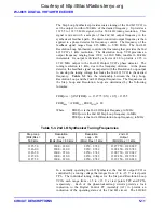
The oscillator consists of a six-band VCO, of which five of the bands are
currently used. Band 4 is not used. Each band covers a portion of the
required frequency range. Data for tuning of the 1st LO synthesizer is
provided by the serial control bus originating in the Digital Control PC
Assembly (A2). The serial data (DATA1, P1, pin 15), and its associated
clock (CLK1, P1, pin 14) and strobe (1ST LO STB, P1, pin 11) lines
carries three 8-bit tuning bytes that contain the VCO band select,
÷
N/
÷
A
tuning, and the VCO loop gain factor (G0/G1) data. The serial data is
converted to a group of eighteen parallel control lines that control the
entire synthesizer operation. Test points TP11 through TP16 provide an
indication of the VCO band switching. At these test points, a +10 V level
indicates that the associated band is active, and a level of approximately
0V indicates an inactive band.
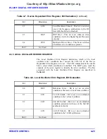
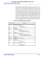
Table 5-2
lists the switching frequencies
for the VCO bands and the appropriate switching voltage test points. Test
points TP26 through TP35 contain the most current
÷
N and
÷
A data. Test
points TP21 and TP22 contain the loop gain factors. These test points may
be viewed to verify that tuning data is being updated by the Digital Control
PC Assembly (A2).
Courtesy of http://BlackRadios.terryo.org
Содержание WJ-8611
Страница 3: ...A B blank Courtesy of http BlackRadios terryo org...
Страница 4: ...THIS PAGE INTENTIONALLY LEFT BLANK Courtesy of http BlackRadios terryo org...
Страница 19: ...1 i SECTION 1 GENERAL DESCRIPTION Courtesy of http BlackRadios terryo org...
Страница 20: ...1 ii THIS PAGE INTENTIONALLY LEFT BLANK Courtesy of http BlackRadios terryo org...
Страница 28: ...WJ 8611 DIGITAL VHF UHF RECEIVER 1 8 GENERAL DESCRIPTION NOTES Courtesy of http BlackRadios terryo org...
Страница 29: ...2 i SECTION 2 INSTALLATION Courtesy of http BlackRadios terryo org...
Страница 30: ...2 ii THIS PAGE INTENTIONALLY LEFT BLANK Courtesy of http BlackRadios terryo org...
Страница 47: ...3 i SECTION 3 LOCAL OPERATION Courtesy of http BlackRadios terryo org...
Страница 48: ...3 ii THIS PAGE INTENTIONALLY LEFT BLANK Courtesy of http BlackRadios terryo org...
Страница 84: ...WJ 8611 DIGITAL VHF UHF RECEIVER 3 36 LOCAL OPERATION NOTES Courtesy of http BlackRadios terryo org...
Страница 85: ...4 i SECTION 4 REMOTE CONTROL Courtesy of http BlackRadios terryo org...
Страница 86: ...4 ii THIS PAGE INTENTIONALLY LEFT BLANK Courtesy of http BlackRadios terryo org...
Страница 119: ...5 i SECTION 5 CIRCUIT DESCRIPTIONS Courtesy of http BlackRadios terryo org...
Страница 120: ...5 ii THIS PAGE INTENTIONALLY LEFT BLANK Courtesy of http BlackRadios terryo org...
Страница 142: ...WJ 8611 DIGITAL VHF UHF RECEIVER 5 22 CIRCUIT DESCRIPTIONS NOTES Courtesy of http BlackRadios terryo org...
Страница 143: ...6 i SECTION 6 MAINTENANCE Courtesy of http BlackRadios terryo org...
Страница 144: ...6 ii THIS PAGE INTENTIONALLY LEFT BLANK Courtesy of http BlackRadios terryo org...
Страница 167: ...7 i SECTION 7 REPLACEMENT PARTS LIST Courtesy of http BlackRadios terryo org...
Страница 168: ...7 ii THIS PAGE INTENTIONALLY LEFT BLANK Courtesy of http BlackRadios terryo org...
Страница 243: ...A i APPENDIX A 8611 SM SIGNAL MONITOR OPTION Courtesy of http BlackRadios terryo org...
Страница 244: ...A ii THIS PAGE INTENTIONALLY LEFT BLANK Courtesy of http BlackRadios terryo org...
Страница 267: ...FP i FOLDOUTS Courtesy of http BlackRadios terryo org...
Страница 268: ...FP ii THIS PAGE INTENTIONALLY LEFT BLANK Courtesy of http BlackRadios terryo org...
Страница 298: ...Courtesy of http BlackRadios terryo org...
Страница 300: ...Courtesy of http BlackRadios terryo org...
Страница 301: ...Courtesy of http BlackRadios terryo org...


