


Manual, Ultra High Sensitivity Aerosol Spectrometer (UHSAS)
DOC-0210 Rev E-4
1 8
© 2017 DROPLET MEASUREMENT TECHNOLOGIES
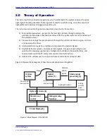
After a trigger is generated, a small delay occurs to allow the particle signal to reach its
maximum. Then the four ADCs sample the four peak-held particle signals from the four gain
stages. The system first examines the highest gain (G3), then the next-highest, and so on. The
first ADC that is not in saturation is the valid particle ADC. The value of this ADC is read and
compared to a look-up table of bin boundaries previously loaded into memory via the
Map
tab.
Depending on where in the look-up table the particle signal belongs, a counter for the
appropriate bin is incremented. (Note that there are some conditions which will invalidate a
particle event—for example, if the event falls outside certain timing requirements.) After the
particle signal is sampled, a reset is sent to the peak-hold circuit and the cycle repeats for the
next particle.
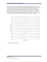
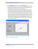
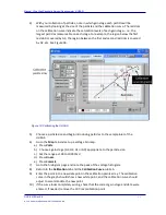
The look-up table is the crux of the peak-height analysis in the UHSAS. The user can reset this
table at any time to generate a new bin mapping. Using the relative gains and the calibration
curve and points, the instrument automatically converts the bin boundaries to a mapping of
voltages at each of the gain stages. The mapping process is transparent to the user and occurs
every time a bin map is committed to the instrument.
2.4.2
Monitoring and Control
The digital electronics also monitor and control various onboard systems, as follows.
Monitoring and Control:
Monitoring Only:
•
The mass flow controller, which regulates
the sample flow
•
The pump laser diode—this is regulated
through enable/disable lines and through
current and temperature set points
•
The electronic flow meters for the sheath
and purge flows (flows are controlled by
mechanically-actuated needle valves)
•
The laser reference from the reference
photodiode (sampled on an ADC)
•
The molecular scattering level (sampled on
an ADC)
•
Additional housekeeping parameters, such
as the electronics box temperature and
ambient barometric pressure.
1
Set points for the controlled parameters are stored in configuration files. All monitored
parameters are logged with the sample data.
1
In the future, these readings may be used for correcting flow meters and noise-cancellation
circuitry.


