


9
10.Verify that the
LED is lit. To confirm that power is correctly connected, the front panel status LED
will flash RED and GREEN, indicating that the firmware is booting up.
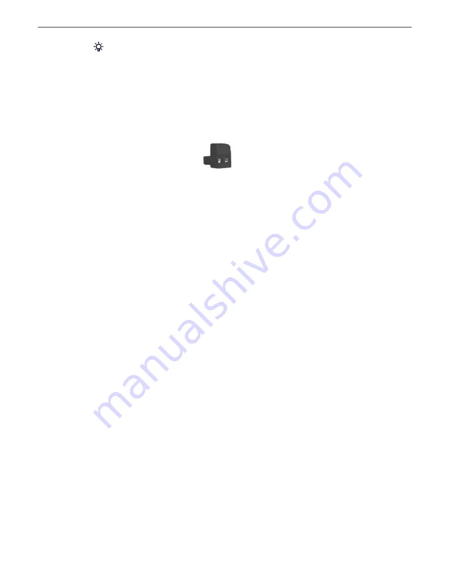
An optional version of the unit is powered by a screw-on plug, as seen in the image below.
Close-up view of the screw-on power connector
To connect the unit's power supply with a screw on plug, follow these steps:
1. Plug in the power connector to the rear panel of the device.
2. Twist the collar of the plug to lock in place.
3. Plug in the wall transformer to a power outlet.
LAN Connection
5.2
To connect the NetGuardian to the LAN, insert a standard RJ45 Ethernet cable into the 10/100BaseT
Ethernet port on the back of the unit. If the LAN connection is OK, the LNK LED will light
SOLID
GREEN
.
Serial Connection
5.3
The NetGuardian has 5 build options for it's serial / dialup port. You can order your port as a
Yost RS-
232, RS-485, 4-wire 202 RJ45/4-pin connection
, with a
dial-up modem
, or 900Mhz wireless
interface. The serial port is located on the back panel, where it is labeled "Primary."


