60
DPMS XPQ User Manual
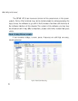
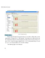
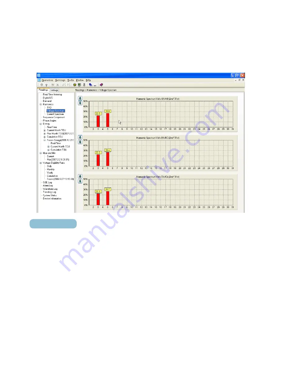
A chart in the software is shown below:
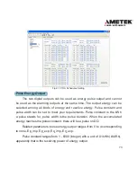
Fig 4.3 Voltage Spectrum
Phase angle
Phase angle indicates the angle between U1 and other voltage and current
parameters. It ranges from 0 - 360 degrees. This function is to help you find out
the relationship between all input signals avoiding incorrect wiring. When it is
set to “2LL”, it gives the phase angle of u23, i1, i2, i3 corresponding to u12 and
u2, u3, i1, i2, i3 corresponding to u1 for other settings.
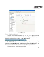
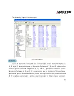
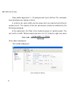
The following figure is an example:
Содержание XPQ
Страница 1: ...POWER INSTRUMENTS DPMS XPQ Multi Function Power Meter User Manual 1087 332...
Страница 2: ......
Страница 7: ...Chapter 1 Introduction Purpose Application Area Functions DPMS XPQ Series 5...
Страница 13: ...Chapter 2 Installation Appearance and Dimensions Installation Method Wiring 11...
Страница 28: ...26 DPMS XPQ User Manual 2 3LN 3CT with 2 CTs Fig 2 19 3LN 3CT with 2 CTs 3 2LN 2CT Fig 2 20 2LN 2CT...
Страница 29: ...27 POWER INSTRUMENTS 4 2LN 1CT Fig 2 21 2LN 1CT 5 2LL 3CT Fig 2 22 2LN 3CT Acuvim X Fig 2 21 2LN 1CT...
Страница 30: ...28 DPMS XPQ User Manual 6 2LL 2CT Fig 2 23 2LL 2CT 7 2LL 1CT Fig 2 24 2LL 1CT...
Страница 59: ...Chapter 4 Function and Software Functionality and Utility Software 57...
Страница 68: ...66 DPMS XPQ User Manual Here is an example Fig 4 7 Demand Here is to set demand...
Страница 90: ...88 DPMS XPQ User Manual Fig 4 20 Voltage Eligibility Ratio...
Страница 126: ...124 DPMS XPQ User Manual...
Страница 127: ...125 Appendix Appendix A Technical Data and Specifications Appendix B Ordering Information...
Страница 133: ......

