50
DPMS XPQ User Manual
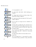
output to DO2. On the panel, it is set as decimal but in
the register it is binary, so it needs conversion.
36, 37: The same as DO1 and DO2.
38: Two alarm rules can be logically “and” by controlling
the logic switch. When two alarm rules are logical and
the alarming works, only both of them are true. This
function is controlled by the low 8 bits of a 16-bit register;
each bit is corresponding to a group. “1” means this
function is turned on and “0” means off.
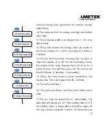
39: Any change on DI can trigger waveform capturing.
It is controlled by a 16-bit register. Bit1, bit0 controls
DI1, bit3, bit2 controls DI2, bit4, bit5 controls DI3 and
bit7, bit6 controls DI4. “00” stands for no capturing, “01”
capture from off to on, “10” from on to off and “11” for any
changes.
Note:
You should convert the hex number to a binary
number first.
40: Under the condition of a blank record, setting “yes”
can initialize one record of the waveform capture.
41: After every interval, it records the value of frequency,
UA (UAB), IA, UB (UBC), IB, UC (UCA), IC. The values
are called trending records. The interval can be set from
1min - 60min with a default of 60min.
42: Display format is MM: DD: YYYY.
43: display format is hh:mm:ss.
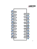
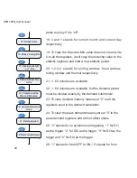
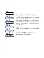
32: Relay for alarming
33: Alarming records
enable
34: Alarming output to
DO1
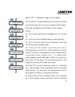
30: Alarming enable
31: Backlight flashing
V/A
V/A
V/A
V/A
V/A
35: Alarming output to
DO2
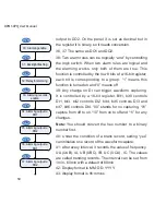
36: Alarming output to
RO1
V/A
V/A
37: Alarming output to
RO2
V/A
Содержание XPQ
Страница 1: ...POWER INSTRUMENTS DPMS XPQ Multi Function Power Meter User Manual 1087 332...
Страница 2: ......
Страница 7: ...Chapter 1 Introduction Purpose Application Area Functions DPMS XPQ Series 5...
Страница 13: ...Chapter 2 Installation Appearance and Dimensions Installation Method Wiring 11...
Страница 28: ...26 DPMS XPQ User Manual 2 3LN 3CT with 2 CTs Fig 2 19 3LN 3CT with 2 CTs 3 2LN 2CT Fig 2 20 2LN 2CT...
Страница 29: ...27 POWER INSTRUMENTS 4 2LN 1CT Fig 2 21 2LN 1CT 5 2LL 3CT Fig 2 22 2LN 3CT Acuvim X Fig 2 21 2LN 1CT...
Страница 30: ...28 DPMS XPQ User Manual 6 2LL 2CT Fig 2 23 2LL 2CT 7 2LL 1CT Fig 2 24 2LL 1CT...
Страница 59: ...Chapter 4 Function and Software Functionality and Utility Software 57...
Страница 68: ...66 DPMS XPQ User Manual Here is an example Fig 4 7 Demand Here is to set demand...
Страница 90: ...88 DPMS XPQ User Manual Fig 4 20 Voltage Eligibility Ratio...
Страница 126: ...124 DPMS XPQ User Manual...
Страница 127: ...125 Appendix Appendix A Technical Data and Specifications Appendix B Ordering Information...
Страница 133: ......

