50 Hz: G625 - G690 - G750XW/XF
OPERATION & MAINTENANCE MANUAL
52
60 Hz: G655 - G750 - G800 - G850XW/XF
INSTALLATION NOZZLE
1.
Clean seat in cylinder head.
2.
Insert nozzle holder with new gasket.
3.
Tighten union nut with 12 kgf•m.
4.
Install injection lines free of constraint. Install leak fuel
lines, screw delivery pipe at nozzle holder and at the
injection pump.
CAUTION
The injection lines are designed for high operating
pressure and should be handled with particular care.
When mounting the pipes to the engine ensure they
are properly fitted.
Do not bend pipes when replacing the nozzles.
Do not mount any misshapen pipes.
Avoid bending pipe ends by more than 2 to 3
degrees.
In case of faults in the injection system which might
have resulted in excessive operating pressures,
replace both the failed part and the injection line.
NOTE FOR CLEANING NOZZLE
•
Clean nozzle body externally from soot and carbon.
When cleaning several nozzles at the same time,
make sure nozzle bodies and needles are not mixed
up. Visually inspect needle and body.
•
Do not clean the nozzle if the seat of the needle is
indented or the pintle is damaged. If this occurs the
nozzle should be replaced.
•
Clean annular groove with scraper over full
circumference. Wash out dislodged carbon deposits
and dirt.
•
Scrape needle seat with cleaning cutter. Dip cutter in
test oil before use. The cutter can also be clamped in
a lathe.
•
Polish needle seat with wooden cleaning tool by
chucking the needle in a lathe at the pintle end.
•
Clean the spray holes of nozzles by chucking a
cleaning needle of suitable diameter in the collet. If
the carbon deposits in the spray holes cannot be
removed by rotating and pressing, have the needle
project only slightly from the collet and drive out the
carbon by lightly tapping on the tool.
•
Before reassembly thoroughly wash nozzle body and
needle in clean test oil.
•
Hold the needle at the pintle end only; to avoid
corrosion do not touch the lapped surfaces of the
needle with your fingers.
•
Thoroughly clean all other parts of the nozzle holder
with clean fuel.
•
Check nozzle discharge pressure in nozzle tester.
The edge-type filter should not be pressed into the
nozzle holder by more than approximately 5mm. If
this depth is exceeded the injector must be replaced.
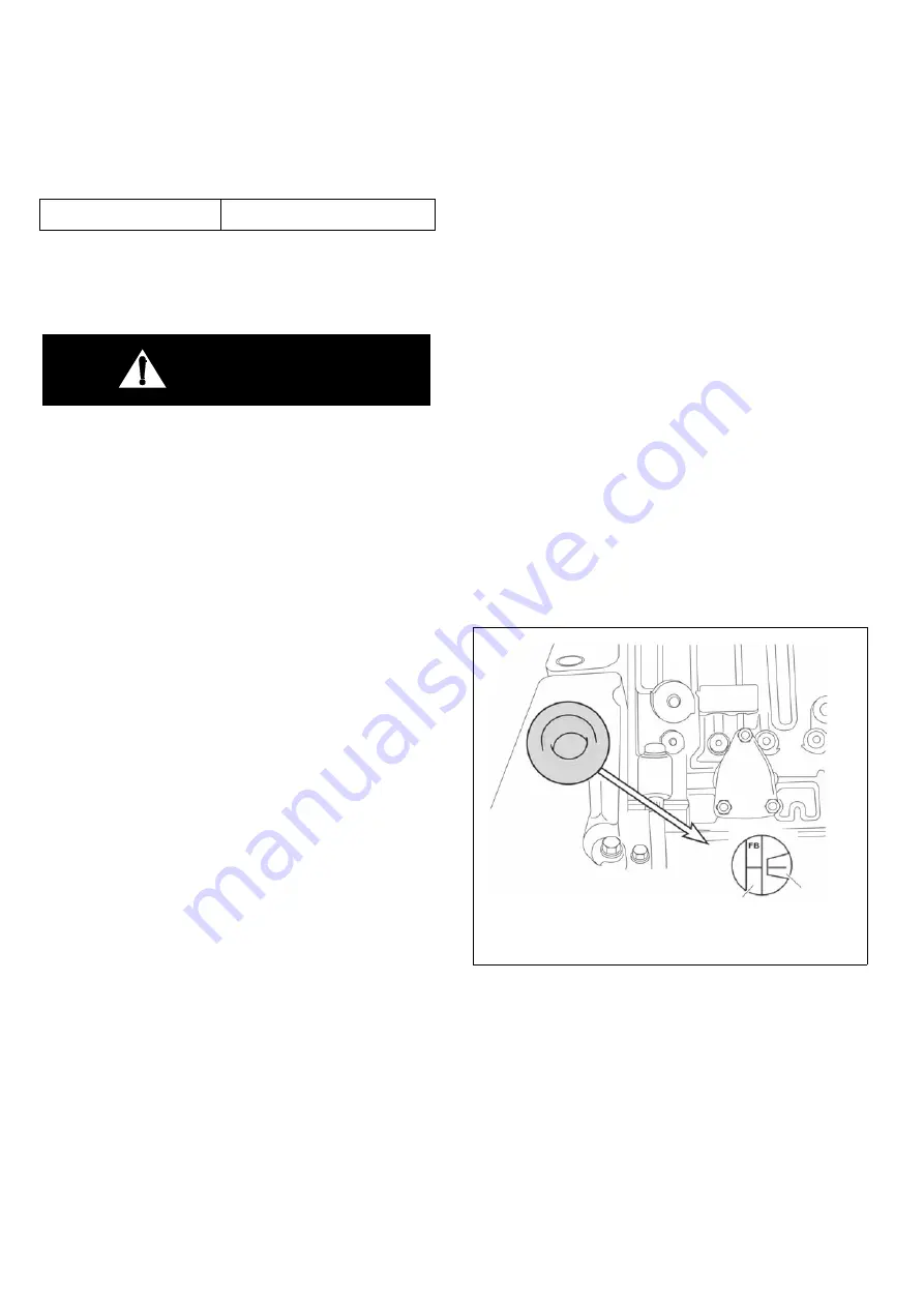
CHECKING THE INJECTION TIMING
1.
Remove the plug screw on the flywheel housing
cover.
NOTE:
In some cases it is necessary to remove the cover
assembly.
2.
Turn the crank pulley so that the mark on pointer
provided on the injection pump coincides with
matching mark (FB) on the flange surface of the drive
gear.
Torque
12 kgf•m
DV2213164A_K
Pointer
Flange
Содержание G625XF
Страница 2: ......
Страница 4: ...50 Hz G625 G690 G750XW XF OPERATION MAINTENANCE MANUAL 4 60 Hz G655 G750 G800 G850XW XF ...
Страница 6: ...50 Hz G625 G690 G750XW XF OPERATION MAINTENANCE MANUAL 6 60 Hz G655 G750 G800 G850XW XF ...
Страница 104: ...50 Hz G625 G690 G750XW XF OPERATION MAINTENANCE MANUAL 104 60 Hz G655 G750 G800 G850XW XF WIRING DIAGRAMS ...
Страница 106: ......


