58
G20, 30, 40 SIIIA Operation & Maintenance Manual
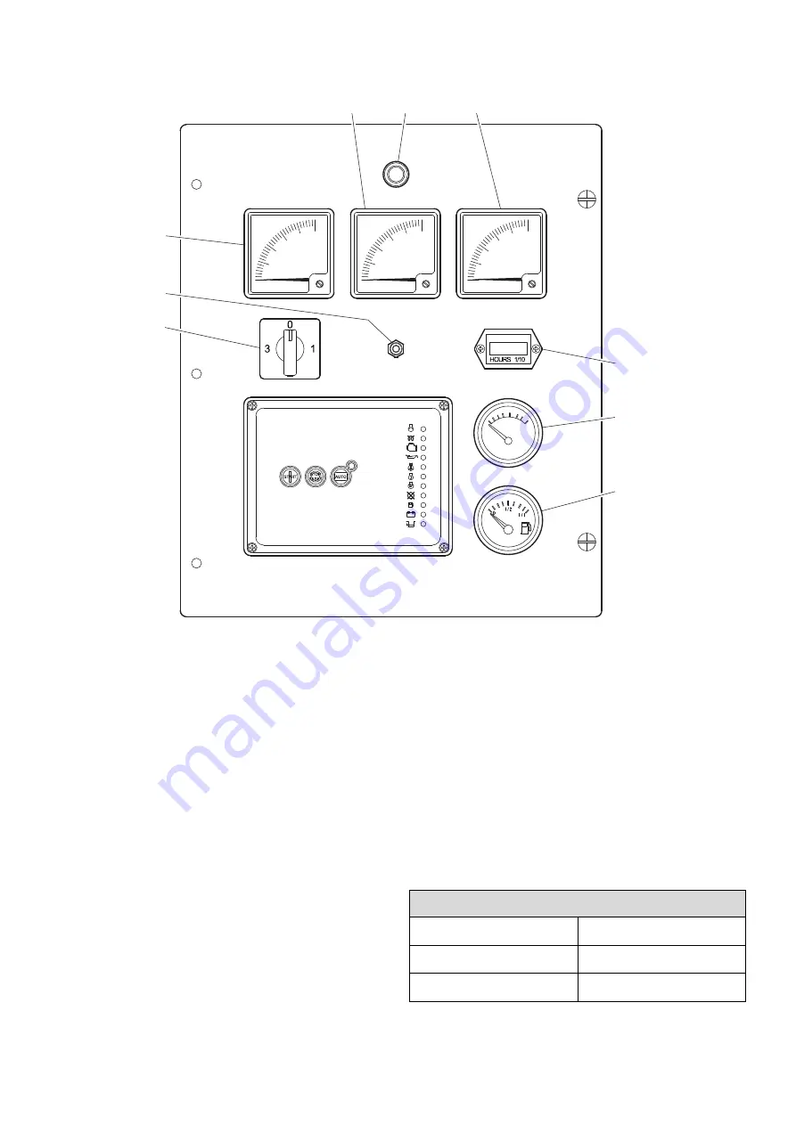
GENERATOR CONTROL PANEL (ANALOG CONTROLLER)
Figure 24
Meters
1.
AC VOLTS -
Indicates the generator output voltage.
2.
AC AMPERES -
Indicates the generator load in
amperes corresponding to AMPERAGE OUTPUT
MONITOR switch position.
3.
Hertz -
Indicates frequency of generator output.
4.
Panel Lamp -
Illumination only.
5.
Battery Voltage -
Indicates battery charging voltage.
6.
Fuel -
Indicates fuel level in tank.
7.
Hourmeter -
Records running time for maintenance.
Monitor Switches
8.
Amperage Output -
Selects the line (phase)
amperage to be displayed on the AC Ammeter.
9.
Voltage Adjust Potentiometer -
Turn to adjust
generator output voltage.
Protection / Regulation
10.
3 Phase Direct Hookup Connections -
L1, L2, L3, N
(neutral), PE (Protective Earth). (Not shown.)
11.
Fuse Holders -
Fuses for voltage output meter. (Not
shown.)
12.
Residual Current Release Device (RCD) -
Provides
earth leakage protection. (Not shown.)
13.
Main Circuit Breaker -
(Not shown.)
14.
Alarm Horn -
(Not shown but is located on back of
control box.)
V
A
Hz
5
7
6
1
3
4
8
2
9
VOLTAGE ADJUSTMENT RANGE
Line - Neutral
Line - Line
L
1
-N, L
2
-N, L
3
-N
L
1
-L
2
, L
1-
L
3
, L
2 -
L
3
207V - 253V
360V - 440V
Содержание G20 SIIIA
Страница 2: ......
Страница 4: ...4 G20 30 40 SIIIA Operation Maintenance Manual ...
Страница 10: ...10 G20 30 40 SIIIA Operation Maintenance Manual ...
Страница 15: ...15 G20 30 40 SIIIA Operation Maintenance Manual WARNING Flammable liquid ...
Страница 20: ...20 G20 30 40 SIIIA Operation Maintenance Manual ...
Страница 121: ......
Страница 122: ...Doosan Bobcat EMEA s r o U Kodetky 1810 263 12 Dobříš Czech Republic www doosanportablepower eu ...


