


10
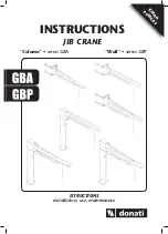
INSTRUCTIONS JIB CRANE SERIES GBA - GBP
MAN05MGO5
46ERSIONCANTILEVERVERSION
$IMENSIONS-AND.FORWALLMOUNTEDJIBCRANESSEECORRESPONDINGHEIGHTSRELATIVETOCOLUMNMOUNTEDJIBCRANES
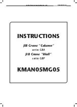
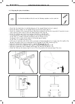
Wall-mounted jib crane - Rotation 250°
#OLUMNMOUNTEDJIBCRANE2OTATIONª
,IFTING
capacity
2 A R
3 A R
4 B S
5 B S
125
kg
m
S
Arm
T01A20 170
248
644
200
594
150
15
63
T01A30 170
248
644
200
594
150
15
79
T01B40 170
288
644
200
594
150
15
125
T01B50 170
288
644
200
594
150
15
147
A
Overall dimensions (mm)
Type
GBP series wall-mounted jib cranes – T version
W
eight
of
crane
B
C
D
E
F
Ø
kg
4 A R
5 A R
T01A40 170
248
644
200
594
150
15
95
T01A50 170
248
644
200
594
150
15
111
3 5 T30R40 2800 228
190
655
160
12 148 18.2
3 5 T30R50 2800 228
190
715
160
12 164 18.2
6
F Z
1600
T03F67 255
590
1240
300
1160
220
34
610
190
1270
450
2
E V
3
E V
4
F Z
5
F Z
2000
T03E20 255
499
1240
300
1160 220
34
267
T03E30 255
499
1240
300
1160 220
34
324
T03F40 255
540
1240
300
1160 220
34
400
T03F50 255
590
1240
300
1160 220
34
535
4 6 T40V20 3580 443
210
900
360
20 564 64
4 6 T40V30 3580 443
210
960
360
20 621 64
4 6 T40Z40 3540 513
210
1070
400
20 780 75.2
210
1220
450
3 5 T30R20 2800 228
190
595
160
12 116 18.2
3 5 T30R30 2800 228
190
655
160
12 132 18.2
3 5 T30S40 2760 274
190
725
200
12 200 22.8
3 5 T30S50 2760 274
190
785
200
12 222 22.8
2 B S
3 B S
4 C T
5 C T
6 D U
6 E V
7 E V
250
T01B20 170
288
644
200
594
150
15
81
T01B30 170
288
644
200
594
150
15
103
T02C40 210
346
930
250
870
190
22
195
T02C50 210
346
930
250
870
190
22
226
T02D62 210
406
930
250
870
190
22
340
T03E62 255
500
1240
300
1160
220
34
410
T03E72 255
500
1240
300
1160
220
34
555
3 5 T30S20 2760 274
190
665
200
12 156 22.8
3 5 T30S30 2760 274
190
725
200
12 178 22.8
3.5 5.5 T35T40 3212 323
190
800
240
17 320 35
3.5 5.5 T35T50 3212 323
190
860
240
17 351 35
190
1000
300
4 6 T40V62 3640 443
190
1065
300
20 705 64
4 6 T40V72 3580 443
190
1135
360
20 852 64
2 C T
3 C T
4 D U
5 D U
6 E V
6 F Z
7 E V
7 F Z
500
T02C20 210
346
930
250
870
190
22
134
T02C30 210
346
930
250
870
190
22
165
T02D40 210
406
930
250
870
190
22
256
T02D50 210
406
930
250
870
190
22
298
T03E65 255
500
1240
300
1160
220
34
482
T03E75 255
540
1240
300
1160
220
34
596
3.5 5.5 T35T20 3212 323
190
740
240
17 260 35
3.5 5.5 T35T30 3212 323
190
800
240
17 290 35
3.5 5.5 T35U40 3152 386
190
880
300
17 430 43.5
3.5 5.5 T35U50 3152 386
190
940
300
17 472 43.5
4 5 T40V65 3580 443
190
1140
360
20 779 64
4 6 T40Z62 3580 513
190
1140
360
20 864 75.2
4 4 T40V75 3540 443
190
1270
400
20 893 64
4 6 T40Z72 3540 513
190
1270
400
20 978 75.2
2
D U
3
D U
4
E V
5
E V
6
F Z
7
F Z
1000
T02D20 210
406
930
250
870 190
22
172
T02D30 210
406
930
250
870 190
22
214
T03E40 255
499
1240
300
1160 220
34
381
T03E50 255
499
1240
300
1160 220
34
438
T03F65 255
540
1240
300
1160 220
34
530
T03F75 255
590
1240
300
1160
220
34
688
3.5 5.5 T35U20 3152 386
190
820
300
17 346 43.5
3.5 5.5 T35U30 3152 386
190
880
300
17 388 43.5
4 6 T40V40 3580 443
190
945
360
20 678 64
4 6 T40V50 3580 443
190
1005 360
20 735 64
4 4 T40Z65 3540 513
190
1190 400
20 912 75.2
190
1270 450
Type
Overall dimensions
Weight
GBA series column-mounted jib cranes – T version
Column
by
m
Crane
Under
beam
h
G
M
N
T
(IPE)
6
kg
kg
Size
of
jib
crane
Bracket
Column
H
m
T
otal
height
base
max.
63
KMAN05MG05
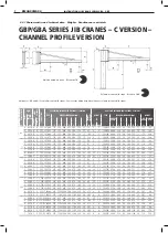
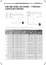
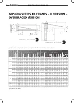
GBP/GBA SERIES JIB CRANES – T VERSION –
CANTILEVER VERSION
LIFTING
CAPACITY
ARM
SIZE OF
JIB CRANE
GBP SERIES WALL-MOUNTED JIB CRANES - T VERSION
GBA SERIES COLUMN-MOUNTED CRANE - VERSION T
S
TYPE
OVERALL DIMENSIONS (mm)
WEIGHT JIB CRANE
HEIGHT
TYPE
OVERALL DIMENSIONS (mm)
WEIGHT
BRA
CKET
COLUMN
A
B
C
D
E
F
Ø
H
m
UNDER
BEAM
JIB
CRANE
COLUMN
BY m
kg
m
kg
BASE MAX.
h
G
M
N
T
(IPE)
Δ
kg
kg
63
4
A
R
T01A40 170 248 644 200 594 150 15
95
3
5
T30R40
2800 228 190 655 160 12
148
18.2
5
A
R
T01A50 170 248 644 200 594 150 15
111
3
5
T30R50
2800 228 190 715 160 12
164
18.2
125
2
A
R
T01A20 170 248 644 200 594 150 15
63
3
5
T30R20
2800 228 190 595 160 12
116
18.2
3
A
R
T01A30 170 248 644 200 594 150 15
79
3
5
T30R30
2800 228 190 655 160 12
132
18.2
4
B
S
T01B40 170 288 644 200 594 150 15
125
3
5
T30S40
2760 274 190 725 200 12
200
22.8
5
B
S
T01B50 170 288 644 200 594 150 15
147
3
5
T30S50
2760 274 190 785 200 12
222
22.8
250
2
B
S
T01B20 170 288 644 200 594 150 15
81
3
5
T30S20
2760 274 190 665 200 12
156
22.8
3
B
S
T01B30 170 288 644 200 594 150 15
103
3
5
T30S30
2760 274 190 725 200 12
178
22.8
4
C
T
T02C40 210 346 930 250 870 190 22
195
3.5
5.5 T35T40
3212 323 190 800 240 17
320
35
5
C
T
T02C50 210 346 930 250 870 190 22
226
3.5
5.5 T35T50
3212 323 190 860 240 17
351
35
6
D
U
T02D62 210 406 930 250 870 190 22
340
190 1000 300
6
E
V
T03E62 255 500 1240 300 1160 220 34
410
4
6
T40V62
3640 443 190 1065 300 20
705
64
7
E
V
T03E72 255 500 1240 300 1160 220 34
555
4
6
T40V72
3580 443 190 1135 360 20
852
64
500
2
C
T
T02C20 210 346 930 250 870 190 22
134
3.5
5.5 T35T20
3212 323 190 740 240 17
260
35
3
C
T
T02C30 210 346 930 250 870 190 22
165
3.5
5.5 T35T30
3212 323 190 800 240 17
290
35
4
D
U
T02D40 210 406 930 250 870 190 22
256
3.5
5.5 T35U40 3152 386 190 880 300 17
430
43.5
5
D
U
T02D50 210 406 930 250 870 190 22
298
3.5
5.5 T35U50 3152 386 190 940 300 17
472
43.5
6
E
V
T03E65 255 500 1240 300 1160 220 34
482
4
5
T40V65
3580 443 190 1140 360 20
779
64
6
F
Z
4
6
T40Z62
3580 513 190 1140 360 20
864
75.2
7
E
V
T03E75 255 540 1240 300 1160 220 34
596
4
4
T40V75
3540 443 190 1270 400 20
893
64
7
F
Z
4
6
T40Z72
3540 513 190 1270 400 20
978
75.2
1000
2
D
U
T02D20 210 406 930 250 870 190 22
172
3.5
5.5 T35U20 3152 386 190 820 300 17
346
43.5
3
D
U
T02D30 210 406 930 250 870 190 22
214
3.5
5.5 T35U30 3152 386 190 880 300 17
388
43.5
4
E
V
T03E40 255 499 1240 300 1160 220 34
381
4
6
T40V40
3580 443 190 945 360 20
678
64
5
E
V
T03E50 255 499 1240 300 1160 220 34
438
4
6
T40V50
3580 443 190 1005 360 20
735
64
6
F
Z
T03F65 255 540 1240 300 1160 220 34
530
4
4
T40Z65
3540 513 190 1190 400 20
912
75.2
7
F
Z
T03F75 255 590 1240 300 1160 220 34
688
190 1270 450
1600
6
F
Z
T03F67 255 590 1240 300 1160 220 34
610
190 1270 450
2000
2
E
V
T03E20 255 499 1240 300 1160 220 34
267
4
6
T40V20
3580 443 210 900 360 20
564
64
3
E
V
T03E30 255 499 1240 300 1160 220 34
324
4
6
T40V30
3580 443 210 960 360 20
621
64
4
F
Z
T03F40 255 540 1240 300 1160 220 34
400
4
6
T40Z40
3540 513 210 1070 400 20
780
75.2
5
F
Z
T03F50 255 590 1240 300 1160 220 34
535
210 1220 450
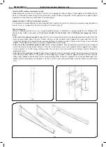
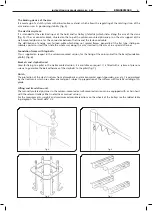
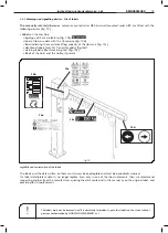
Heights M* and N* for wall-mounted jib cranes. See corresponding heights relative to column-mounted jib cranes.
Wall-mounted jib crane - Rotation 250°
Column-mounted jib crane - Rotation 290°


