background image

27

Dalamatic Insertable Dust Collectors – Series DLM V

Installation, Operation and Maintenance Manual

  4  Undo and remove bolt in end of motor shaft holding the hub retaining washer.
  5  Remove motor key by easing it out from keyway.
  6  Using the location grooves machined into hub, pull impeller from motor shaft 

and out through the front of fan case.

  7  Slide spacer off motor shaft.
  8  Remove the 4 nuts, bolts and washers holding motor to pedestal.
  9  The motor can now be removed using suitable lifting equipment, taking 

care not to damage sealing washer placed between motor endplate and 
fan casing.

 10  Place the new motor on support pedestal and locate rubber sealing washer 

between fan case and motor.

 11  Position motor on pedestal and secure loosely by replacing the 4 nuts, bolts 

and washers.

 12  Locate motor key into keyway on motor shaft.
 13  Push motor shaft spacer onto motor shaft.
 14  Align keyway of impeller hub onto key and slide impeller onto motor shaft.
 15  Replace hub retaining washer and shakeproof washer.  Apply thread lock 

to motor end shaft bolt and replace bolt, ensuring impellor is pushed back 
onto spacer.

 16  Apply thread locks to grub screws holding hub and tighten into place.
 17  Locate impeller, according to the dimension taken during removal, by moving 

motor along pedestal, ensuring motor remains square to fan case.

MAINTENANCE

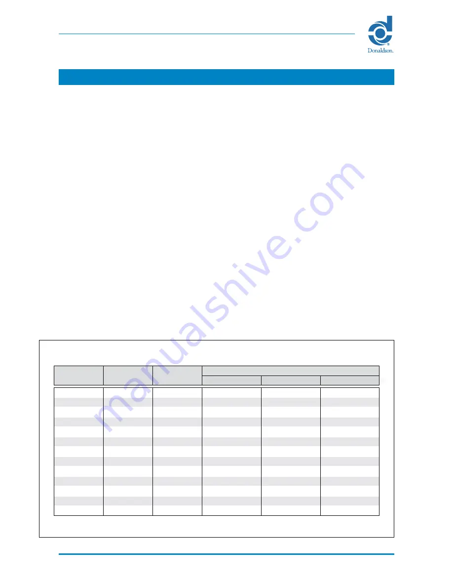
TABLE 1 – TORQUE VALUES FOR BOLTS WITH ISO METRIC THREAD

* For nuts and bolts to ISO 4017.

8 mm 

1 mm 

20.1 mm² 

10.4 Nm 

15.3 Nm 

17.9 Nm

7 mm 

1 mm 

28.9 mm² 

17.2 Nm 

25 Nm 

30 Nm

8 mm 

1.25 mm 

36.6 mm² 

25 Nm 

37 Nm 

44 Nm

10 mm 

1.5 mm 

58 mm² 

50 Nm 

73 Nm 

86 Nm

12 mm 

1.75 mm 

84.3 mm² 

86 Nm 

127 Nm 

148 Nm

14 mm 

2 mm 

115 mm² 

137 Nm 

201 Nm 

235 Nm

16 mm 

2 mm 

157 mm² 

214 Nm 

314 Nm 

368 Nm

18 mm 

2.5 mm 

192 mm² 

306 Nm 

435 Nm 

509 Nm

20 mm 

2.5 mm 

245 mm² 

432 Nm 

615 Nm 

719 Nm

22 mm 

2.5 mm 

303 mm² 

592 Nm 

843 Nm 

987 Nm

24 mm 

3 mm 

353 mm² 

744 Nm 

1060 Nm 

1240 Nm

27 mm 

3 mm 

459 mm² 

1100 Nm 

1570 Nm 

1840 Nm

30 mm 

3.5 mm 

561 mm² 

1500 Nm 

2130 Nm 

2500 Nm

Nominal 

diameter

Torque value*

Grade 8.8

Thread 

pitch

Stress 

area

Grade 10.9

Grade 12.9

Содержание DLM V Series

Страница 1: ...Dalamatic Insertable Dust Collectors Series DLM V IOM AK0303101 0 Installation Operation and Maintenance Manual...

Страница 2: ...698 IPC OR IPC CONTROLLER PUBLICATION 2699 PT CONTROLLER PUBLICATION 2697 Delta P C01 Controller Delta P C01 IOM AK0303001 PRODUCT RELIABILITY WARRANTY AND SAFE OPERATION MAY BE COMPROMISED BY NOT FOL...

Страница 3: ...located on the left hand side panel of the equipment to which this Manual refers Improper operation of a dust control system may contribute to conditions in the work area or facility that could resul...

Страница 4: ...11 Flat bar stiffening 13 Fitting Dalamatic filter elements 13 Final assembly 13 Compressed air requirements 14 Controller 15 Overload protection 16 Antistatic earthing 16 Interlocks 17 Ex controls 1...

Страница 5: ...ption and range 30 Construction 30 Spare Parts 37 Declaration of Conformity 43 Table 1 Torque values for bolts with ISO metric thread 27 Table 2 Fault location 29 Table 3 Dalamatic Insertable dust col...

Страница 6: ...there may be a risk due to explosion During assembly installation or dismantling of equipment potential ignition sources may occur that were not considered in the risk assessment of the unit in opera...

Страница 7: ...osive dust or is placed in a potentially explosive atmosphere then all motors should be connected to thermal protection devices to prevent them exceeding their maximum surface temperature All electric...

Страница 8: ...r an open outlet For this reason the internal and external atmospheres can be considered the same in terms of any potentially hazardous classification Standard fan assemblies should not exceed 3000 rp...

Страница 9: ...sert Filter bag Filter element Acoustic diffuser when fitted Jet tube Lifting bracket Collector body Mounting flange Manometer connection optional Earthing post antistatic version Terminal box Fan imp...

Страница 10: ...electrical services must be adequately supported All external equipment connected to the outlet e g ducting should be correctly sealed This can be achieved by applying a continuous 5 mm bead of sealin...

Страница 11: ...for weight of equipment supplied by Donaldson Chains must be long enough to ensure that the included angle between diagonal chains is not greater than 90q 4 Lift and position the collector body until...

Страница 12: ...Figure 5 Fitting filter bag on insert frame Figure 6 Placing filter elements into seal frame slots Figure 7 Filter bag seal level with edge of flange Figure 8 Tightening insert clamp Figure 3 Part vie...

Страница 13: ...as shown in fig 6 9 Ensure that filter bag seal is level with edge of flange on insert frame to obtain effective seal see arrow fig 7 10 Fit clamps and tighten nuts using a ratchet and long reach soc...

Страница 14: ...1 Compressed air requirements Dalamatic Insertable dust collectors require an independent supply of clean dry oil free compressed air Details of atmospheric pressure and quantity are given in Table 6...

Страница 15: ...troller It is a requirement of the Supply of Machinery Safety Regulations 1992 to provide adequate isolation and emergency stop facilities Due to the varied nature of site installations this cannot be...

Страница 16: ...particularly important on collectors having antistatic features and or explosion stiffening that the earthing post located adjacent to the symbol shown opposite is properly connected to earth using th...

Страница 17: ...be such that breakdown of any one of the associated pieces of equipment does not cause a complete blockage of the collector For example should the motor of a belt feeder cease to function the collecto...

Страница 18: ...ns for setting up the controller are the same as those for the standard controller PT Controller The PT Controller is a pneumatically operated device which operates the diaphragm valves in sequence th...

Страница 19: ...losion relief panels are venting to a safe area Ensure controller is connected to the correct voltage and that the pulse interval and duration settings are correct For 24V DC ensure polarity is correc...

Страница 20: ...and equipment being served To achieve this equipment should be shut down in the following order 1 Stop main fan only leaving controller and compressed air supply switched on to allow filter elements...

Страница 21: ...istance from the filter element ensuring that a large volume of air is induced by each injection of compressed air This causes a brief powerful reversal of airflow through the filter element flexing t...

Страница 22: ...zards Appropriate personal protection equipment PPE should be used e g dust mask safety hat gloves etc In order to maintain the original collector specification and to ensure the same level of safety...

Страница 23: ...and washers which blank off tapping point hole located in base side panel If exit header is fitted access may be gained by removing the header cover Fit a suitable manometer connection in place of th...

Страница 24: ...from valve 2 Remove the hexagon head set screws and shakeproof washers securing the valve bonnet B 3 The diaphragm and spring if fitted can now be replaced first ensuring the bleed hole pin is not bl...

Страница 25: ...r damage or ageing and ensure that they are properly seated to prevent entry of water This is particularly important where the dust collector is located outside or in a wet atmosphere Faulty seals mus...

Страница 26: ...until properly repaired or replaced Fan assembly removal replacement Isolate electrical power supply 1 Disconnect electrical cables from motor terminal box 2 Remove header cover by undoing toggle fas...

Страница 27: ...d slide impeller onto motor shaft 15 Replace hub retaining washer and shakeproof washer Apply thread lock to motor end shaft bolt and replace bolt ensuring impellor is pushed back onto spacer 16 Apply...

Страница 28: ...and replace outer circle of bolts Adjust impeller so that there is approximately 2 mm clearance between inlet eye and front of impeller and tighten motor fixing fasteners through pedestal and motor fe...

Страница 29: ...s Renew any filter bags that are damaged a Check line voltage phases fan motor connections For Star Delta applications check motor is in Delta a Check electrical connections and transpose if necessary...

Страница 30: ...0 7 m 1 0 m 1 25 m and 1 5 m respectively see Table 3 The dust collector is designed for application in silos bunkers conveyor transfer points etc Variations of the Insertable are available for appli...

Страница 31: ...m2 10 1 5 m DLM V18 15 18 0 m2 12 1 5 m DLM V20 10 20 0 m2 20 1 0 m DLM V21 7 21 0 m2 30 0 7 m DLM V25 12 25 0 m2 20 1 25 m DLM V30 10 30 0 m2 30 1 0 m DLM V30 15 30 0 m2 20 1 5 m DLM V38 12 38 0 m2...

Страница 32: ...pulled over the wire portion of the insert until the sealing ring meets the sealing flange The ring is compressed when the element is clamped into the seal frame effectively isolating the dirty side...

Страница 33: ...lamps The number of seal frames depends on the dust collector size An earthing boss is fitted to all antistatic versions of dust collectors for antistatic earthing see fig 1 Valves figs 1 18 The compr...

Страница 34: ...2 V45 15 V50 12 and V60 15 collectors Product of pressure and capacity 38 63 bar litres DLM V3 7 and V5 12 collectors 59 21 bar litres DLM V4 7 V6 10 V7 5 12 and V9 15 collectors 106 27 bar litres DLM...

Страница 35: ...d V45 15 4 5 bar 65 psig 9 5 m h 5 6 cfm 60 ms NB 12 DLM V50 12 and V60 15 5 2 bar 75 psig 13 7 m h 8 0 cfm 60 ms NB 12 at 25 sec intervals b DLM V3 7 and V5 12 4 1 bar 60 psig 2 6 m h 1 5 cfm 100 ms...

Страница 36: ...380 420 Y 380 420 D 660 690 Y Range 250 280 3 60 D 440 480 3 60 Y 440 480 3 60 D 0 75 1 5 Nameplate details kW 2 2 and above 250 280 D 440 480 Y 440 480 D Range 3 Phase 60 Hz TABLE 8 STANDARD FAN MOT...

Страница 37: ...matic Insertable Dust Collectors Series DLM V Installation Operation and Maintenance Manual Figure 19 Spare parts identification 1 SPARE PARTS DLM V20 10F 10 valve version illustrated 11 2 4 8 9 6 7 5...

Страница 38: ...ric filter bag polypropylene 0 7 m2 1A 3139 2026 1 0 m2 1A 3139 2010 1 25 m2 1A 3139 2057 1 5 m2 1A 3139 2042 1 Fabric filter bag polypropylene antistatic 0 7 m2 1A 3139 2034 1 0 m2 1A 3139 2018 1 25...

Страница 39: ...20 3 60HZ AK 0013256 5 Fan motor KV15 fan 11 0 kW IP55 AK 0013261 380 3 50HZ 220 3 60HZ AK 0013266 The following fan assemblies are used for Dalamatic Insertables without acoustic diffuser 6 F1 fan as...

Страница 40: ...Hz AK 0013372 60 Hz AK 0013382 7 Impellor KV10 fan 50 Hz AK 0013373 60 Hz AK 0013383 7 Impellor KV11 fan 50 Hz AK 0013374 60 Hz AK 0013384 7 Impellor KV15 fan 50 Hz AK 0013375 60 Hz AK 0013385 Access...

Страница 41: ...roller IOM AK0303001 for Delta P C01 Controller Compressed air assembly 11 Diaphragm valve 1A 3189 9011 12 Diaphragm valve service kit item not illustrated 1A 2565 3204 13 Gasket diaphragm valve 1A 31...

Отзывы: