The gas inlet connection is ½ in (20.95mm). Do not connect a tube with an inner diameter lower than
that required by the machine. Consider the consumption to ensure the necessary flow. See table in
section 2. A minimum 1/8-in NPT plugged tapping, accessible for test gauge connection, must be
installed immediately upstream of the gas supply connection to the dryer.
For all types of gas, it is necessary to install a manual valve and a gas filter, and only for LPG gas
install a pressure regulator. Make sure that dirt does not enter the valve during piping.
Once the installation is completed, it is necessary to make the following DRIP TEST:
Turn on the burners. With the help of a brush, apply soapy water to the gas inlet joints. Check if
bubbles form. If so, disassemble the valves, clean them, and reassemble them. Do not use a soap that
is too corrosive. It is also possible to perform the test with a special product designed for it
The dryer and its manually operated appliance main gas valve must be disconnected from the
gas supply piping system during any pressure testing of that system at test pressures in excess
of 1/2 psi (3.5 kPa).
The dryer must be isolated from the gas supply piping system by closing the equipment shutoff valve
during any pressure testing of the gas supply piping system at test pressures equal to or less than 1/2
psi (3.5 kPa).
INSTRUCTIONS FOR CHECKING THE INLET GAS PRESSURE.
PROCEDURE:
1.- Connect the gas input to the ½” “E” connection.
2.- Loosen the bolt in opening “A” of the valve one turn in an anti-clockwise direction
3.- Connect the pressure gauge on opening ”A”.
4.- Check the gas inlet the pressure, it must be between 3.5 (0.87) and 10.5 (2.61) in wc (kPa).
5.- Remove the manometer pipe.
6.- Tighten bolt “A”
7.- Loosen the bolt in opening "B" of the valve one turn in an anti-clockwise direction.
8- Connect the pressure gauge on opening "B".
9- Remove the solenoid valve plug "C".
10- Regulate the gas inlet screw "C" until the required pressure is reached according to the table on
page 22. Do not over-tighten the Nylon bolt as there is a risk of breaking the internal spring and
causing fuel leaks.
11- Replace the solenoid valve plug "C".
12- Remove the manometer pipe.
13- Tighten bolt "B".
(See drawings on pages 19 & 20)
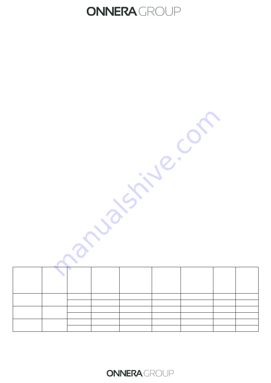
GAS TABLE
Appliance
Input
rating
BTU/h
(kW)
Gas
Minimum
supply
pressure In
wc (kPa)
Maximum
supply
pressure
In wc
(kPa)
Burner
Pressurein
wc (kPa)
Conversion
kit code
Injectors
(mm)
Labels
quantity
25/30/35
Lb
69,983
(20.51)
Propane
8.0 (1.99)
13.0 (3.23)
5.42 (1.35)
12285187
2
.
75
-
Natural
3.5 (0.87)
10.5 (2.61)
2.13 (0.53)
-
4
.
30
3
50 Lb
105,776
(31.00)
Propane
8.0 (1.99)
13.0 (3.23)
5.86 (1.46)
12285186
3
.
30
-
Natural
3.5 (0.87)
10.5 (2.61)
2.05 (0.51)
-
5
.
35
3
65 Lb
80 Lb
139,898
(41.00)
Propane
8.0 (1.99)
13.0 (3.23)
5.30 (1.32)
12285188
2
.
75
-
Natural
3.5 (0.87)
10.5 (2.61)
1.93 (0.48)
-
4
.
40
3
For the gas conversion of the appliance, you need the appropriate injector according to the GAS
TABLE and 3 labels to be placed on the machine once the change has been made.
18


