


7
Fault
Provides a Normally Open (NO) contact point. Any fault condition will close the NO contact. This output can be used to power a
light, relay, or interface to a ship
’s monitoring system. The output on this terminal will be 230 VAC.
SYSTEM OVERVIEW
System Power-up
S
oftware Revision
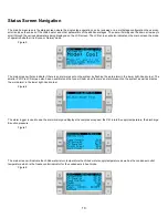
Upon applying power to the system, the display will indicate the software revision number or display it on the main status screen.
VARC is enabled and waiting for user selection.
MODBUS
The VARC comes with a 3 wire Modbus connection as part of the electrical box. This connection is used for multistage configuration,
touchscreen and networking to a boat management system.
Startup
The VARC Chiller controller can be operated as a single or a multistage chiller plant. During initial setup, the system will be configured for
the number of stages and the available options. System is set for Return water control but can be modified for Supply water control if
needed. The user has the option to select between metric values being displayed or Imperial values being displayed during operation of
the system.
In a multistage configuration the user will be able to change the different operating startup modes. The two startup modes are: normal
stage startup or accelerated mode startup. The normal startup is when the system has a time delay between the staging up of the various
stages. Stage one will be initiated and will start its operation once the PID determines that more capacity is required the second stage will
be initiated. While in operation and the system has maintained the chilled water loop and the PID has determined that that no additional
stage is required or has met capacity demand it will reduce the speed of the compressors. The compressors will operate at minimal
speed to maintain the chilled water loop. If the speed of the compressor still exceeds the demand the stage with the most run hours will
be turned off.
The VARC chiller allows the user to select between three operating modes. Econo mode, normal mode and boost mode. These three
modes allow the user to have predefined current limits. The economy mode is the energy efficient mode where the compressor is limited
to default five amp configuration. The normal mode is the typical mode of operation where the current limit is set to 9 Amps for both heat
and cool modes. The boost mode allows the system to run at maximum capacity without current limitation other than the full limits of the
frequency drives which is 12 amps.
Chilled water setpoint will be entered for Cool and Heat mode.
Once enabled, CW and SW pumps will be turned on for operation.
Operational Checks
Once the VARC is enabled the system will conduct pre-startup checks. The VARC program will check all CW flow switches for faults. The
VARC will also check HP and LP (optional) switches for faults.
Individual stage faults will only disable that stage.
Compressor Startup
The VARC utilizes a BLDC compressor that is capable of operating at a very high frequency. This requires that the compressor have a
ramped startup to establish proper lubrication as to not damage the compressor. This startup has a ramp time and a minimal speed
operation that will last for 100 seconds to allow the compressor to properly warm-up before operating at maximum speed.
The compressor minimum on time is 100 seconds and minimum off time is also 100 seconds with a minimum time between starts of 120
seconds. These default parameters allow the compressor to operate in a safe mode that will not damage the compressor.
Содержание VARC 48
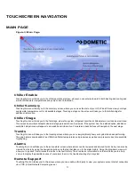
Страница 20: ...18 Appendix I Touchscreen Navigation MAIN PAGE Figure 15 CHILLER ENABLE Figure 16...
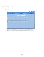
Страница 21: ...19 CHILLER SETPOINTS Figure 17...
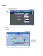
Страница 22: ...20 Figure 18 CHILLER STAGE Figure 19...
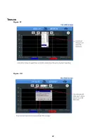
Страница 24: ...22 TRENDS Figure 21 Figure 22...
Страница 25: ...23 ACTIVE ALARMS Figure 23 ALARM HISTORY Figure 24...
Страница 26: ...24 ALARM HELP Figure 25 Figure 26...
Страница 27: ...25 REMOTE SUPPORT Figure 27 REMOTE ENABLE Figure 28...
Страница 28: ...26 REMOTE CONFIGURATION Figure 29...
Страница 41: ...39 Basic wiring diagram...
Страница 55: ...53 7 Use Next or Back to scroll to Display Settings 8 Select Display Settings...
Страница 69: ...67 VARC Standard Wiring Diagram Figure...
Страница 70: ...68 NOTES...
Страница 71: ...69 NOTES...


