


8
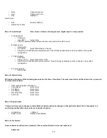
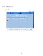
SETPOINTS
Cooling
Cooling setpoint is a VARC adjustable parameter from 42°F (5.56°C) (for Supply control and 48°F Return control) to 55°F (13°C) in one
degree increments. To adjust the cooling setpoint, simply touch the VARC screen and change to desired new setpoint. In cooling mode,
you will not be able to enter a number outside of this range.
Heating
Heating setpoint is a VARC adjustable parameter from 100°F (38°C) to 114°F (45.56°C) in one degree increments. To adjust the
heating setpoint, simply touch the VARC screen and change to desired new setpoint. In heating mode you will not be able to enter a
number outside of this range.
C
ompressor
S
taging
T
ime
Compressor staging time is a VARC adjustable parameter where 2 modes are selectable between normal and accelerated staging.
The accelerated staging is only available in a multistage configuration. The normal staging works the same as the on off syst em where
there is a time delay between the multiple stages driven by the PID loop. The accelerated staging is only available during initial startup
in a multistage configuration. This accelerated startup is when all available stages are turned on simultaneously. The stages will start
the ramp-up process at the same time after the fixed startup delay. After this delay the units will ramp the maximum speed to achieve
maximum capacity.
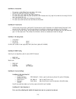
Run Mode
– Cooling
Compressor rotation is active during run mode. The compressor with the lowest running hours will be enabled first and compressor with
the highest running hours will be disabled first.
First stage will be enabled and the compressor will start after CW and SW flows are stable for 10 seconds (default).
First stage will continue to run for 1 minute before enabling the next stage. If the PID loop requires demand, then the next stage will be
enabled with a startup delay of 3 minutes before running up to required speed.
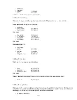
Run Mode
– Reverse Cycle Heating
Compressor rotation is active during run mode. The compressor with the lowest running hours will be enabled first and compressor with
the highest running hours will be disabled first.
Enable Reverse Cycle Heat only for the system.
First stage heating will be enabled and the compressor will start after CW and SW flows are stable for 10 seconds.
First stage will continue to run for 5 minutes before enabling the next heater stage. If the PID loop requires demand, then the next
stage will be enabled with a startup delay of 3 minutes before running up to required speed.
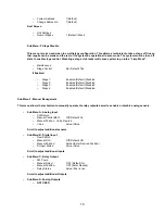
Run Mode
– Electric Heating (optional heater barrel)
Heater rotation is active during run mode. The heater with the lowest running hours will be enabled first and the heater with the highest
running hours will be disabled first.
Enable Electric Heat only for the system.
First stage will be enabled and the electric heater will start after CW flow is stable for 10 seconds.
First stage will continue to run for 5 minutes before enabling the next heater stage. If the PID loop requires demand then the next
stage will be enabled.
OPERATIONAL MODES
PUMP OPERATION
Содержание VARC 48
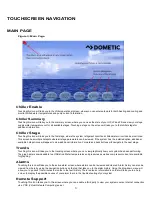
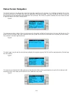
Страница 20: ...18 Appendix I Touchscreen Navigation MAIN PAGE Figure 15 CHILLER ENABLE Figure 16...
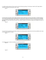
Страница 21: ...19 CHILLER SETPOINTS Figure 17...
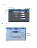
Страница 22: ...20 Figure 18 CHILLER STAGE Figure 19...
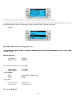
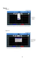
Страница 24: ...22 TRENDS Figure 21 Figure 22...
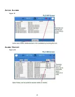
Страница 25: ...23 ACTIVE ALARMS Figure 23 ALARM HISTORY Figure 24...
Страница 26: ...24 ALARM HELP Figure 25 Figure 26...
Страница 27: ...25 REMOTE SUPPORT Figure 27 REMOTE ENABLE Figure 28...
Страница 28: ...26 REMOTE CONFIGURATION Figure 29...
Страница 41: ...39 Basic wiring diagram...
Страница 55: ...53 7 Use Next or Back to scroll to Display Settings 8 Select Display Settings...
Страница 69: ...67 VARC Standard Wiring Diagram Figure...
Страница 70: ...68 NOTES...
Страница 71: ...69 NOTES...


