


6
As the temperature falls, the compressor or electric heat relay will re-energize when the temperature reaches 110°F (43.3°C).
A high temperature fault will be recorded and displayed if the system exceeds the alarm set point. In a high temperature situation,
VARC will not allow the compressor or electric heat relay to be energized. The fault must be manually acknowledged on the active alarm
screen and cleared prior to re-enabling the system or stage.
If a temperature sensor is bad or not connected, the VARC will display an alarm for that sensor.
Freeze Temperature Setpoint
The low limit temperature sensor is continuously monitored whether in Cooling, Reverse Cycle or Electric Heat mode.
This sensor is used to detect a freeze condition in the supply water of the chiller. If the chilled water temperature is sensed to be equal to
or less than 38°F (3.3°C), then the compressor relay will be de-energized, shutting off the compressor. As the temperature rises, the
compressor relay will re-energize when the temperature reaches 42°F (5.6°C).
A low temperature fault will be recorded and displayed if the system falls below the alarm set point. In a low temperature situation,
VARC will not allow the compressor or electric heat relay to be energized. The fault must be manually acknowledged on the active
alarm screen and cleared prior to re-enabling the system or stage.
If a temperature sensor is bad or not connected, the VARC will display an alarm for that sensor.
Condenser Freeze Protection
The system is equipped with a temperature sensor mounted to the condenser coil. This sensor is there to sense the coil temperature. In
heat mode if the coil temperature drops below 40 °F, the VARC controls will automatically lower the speed of the compressor to half the
speed that it was currently running. The disp
lay will indicate “Freeze Defrost” while performing this operation.
PRESSURE TRANSDUCERS
Suction Pressure
The suction pressure is continuously monitored by the VARC. If the suction pressure is below the alarm set point for longer than the
programmed time delay, a fault will occur. This low suction fault will be recorded and displayed on the alarm screen.
The fault must be manually acknowledged via the VARC and cleared prior to re-enabling the system or stage.
Discharge Pressure
The discharge pressure is continuously monitored by the VARC. If the discharge pressure is above the alarm set point for longer than the
programmed time, a fault will occur. This high pressure fault will be recorded and displayed on the alarm screen.
The fault must be manually acknowledged via the VARC and cleared prior to re-enabling the system or stage.
RELAY OUTPUTS
COMP
– Compressor
VARC COMP output will provide switched power to the VFD enable pin for the compressor normal operation.
CWP
– Chilled Water Pump
VARC CWP output will provide switched power to the contactor coils for the chilled water pump.
SWP
– Sea Water Pump
VARC SWP output will provide switched power to the contactor coils for the sea water pump.
RV
– Reversing Valve
VARC RV output will provide switched power to the coils for the reversing valve.
EH
– Electric Heat
VARC EH output will provide switched power to the contactor coils for the electric heat.
Содержание VARC 48
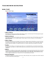
Страница 20: ...18 Appendix I Touchscreen Navigation MAIN PAGE Figure 15 CHILLER ENABLE Figure 16...
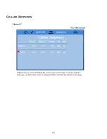
Страница 21: ...19 CHILLER SETPOINTS Figure 17...
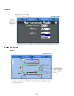
Страница 22: ...20 Figure 18 CHILLER STAGE Figure 19...
Страница 24: ...22 TRENDS Figure 21 Figure 22...
Страница 25: ...23 ACTIVE ALARMS Figure 23 ALARM HISTORY Figure 24...
Страница 26: ...24 ALARM HELP Figure 25 Figure 26...
Страница 27: ...25 REMOTE SUPPORT Figure 27 REMOTE ENABLE Figure 28...
Страница 28: ...26 REMOTE CONFIGURATION Figure 29...
Страница 41: ...39 Basic wiring diagram...
Страница 55: ...53 7 Use Next or Back to scroll to Display Settings 8 Select Display Settings...
Страница 69: ...67 VARC Standard Wiring Diagram Figure...
Страница 70: ...68 NOTES...
Страница 71: ...69 NOTES...


