


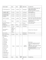


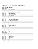


62
Alarm description
Reset
Delay
Alarm
relay
System Action
Corrective Action
EVD EVO Low Superheat
Automatic
Immediate
Yes
Warning Signal
Check for proper refrigerant charge as the
system may be overcharged.
Check water for low flow.
Check EEV movement and functionality.
EVD Evo Low Evaporation
Temperature (LOP)
Automatic
Immediate
Yes
Warning Signal
Check water flows.
Check refrigerant charge.
EVD Evo High Evaporation
Temperature (MOP)
Automatic
Immediate
Yes
Warning Signal
Check refrigerant charge.
EVD Evo Low Suction
Temperature
Automatic
Immediate
Yes
Warning Signal
Check refrigerant charge.
VARC # in Limp Mode
Automatic
Immediate
No
Warning Signal
Check that the PLC is setup for the correct # of
stages, correct and cycle power to the system.
Frost Active
Manual
Immediate
Yes
Off compressor
Low temperature temp switch tripped.
Check water flows.
Check refrigerant charge.
Electric Heat Run Hours
Exceeded
Yes
Off Heater
Check heater voltage
Envelope Alarm
Manual
60 sec
Yes
Off compressor
Clock Board Fault or Not
connected
Automatic
Immediate
Yes
Warning Signal
Inverter model not
compatible
After 15
retries every
60 mins,
must be
reset
Manually
Make sure Power+ is being used
Power+ in Retry
Warning Signal
Check the power supply
Power+ Device Offline
Automatic
30 sec
Yes
Off compressor
Power+ Fault
Alarms Power+ n˚1
Manual
Immediate
Yes
Turns off
compressor
Check the load
Check network control devices and cables
Check the input voltage and rectify the
trouble.
Using a 1000 V megger, check the motor and
motor cables for ground faults.
Check the input and output circuits for phase
loss detection and rectify.
Check the condition of the motor and load
wiring.
None
1:Overcurrent
2:Motor Overload
3:Overvoltage
4:Undervoltage
5:Over Temp
6:Under Temp
7:Overcurrent HW
8:Motor Overtemp
9:Drive Failure
10:CPU Error
11:Param Default
12:DC bus ripple
13:Data Comms Fault
14:Drive thermistor
15:Autotune fault
Alarm description
Reset
Delay
Alarm
relay
System Action
Corrective Action
Содержание VARC 48
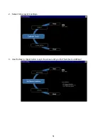
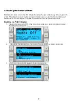
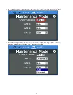
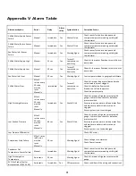
Страница 20: ...18 Appendix I Touchscreen Navigation MAIN PAGE Figure 15 CHILLER ENABLE Figure 16...
Страница 21: ...19 CHILLER SETPOINTS Figure 17...
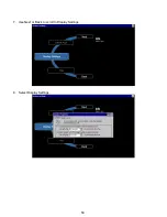
Страница 22: ...20 Figure 18 CHILLER STAGE Figure 19...
Страница 24: ...22 TRENDS Figure 21 Figure 22...
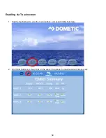
Страница 25: ...23 ACTIVE ALARMS Figure 23 ALARM HISTORY Figure 24...
Страница 26: ...24 ALARM HELP Figure 25 Figure 26...
Страница 27: ...25 REMOTE SUPPORT Figure 27 REMOTE ENABLE Figure 28...
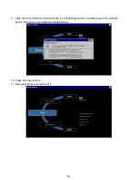
Страница 28: ...26 REMOTE CONFIGURATION Figure 29...
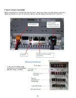
Страница 41: ...39 Basic wiring diagram...
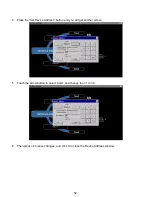
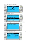
Страница 55: ...53 7 Use Next or Back to scroll to Display Settings 8 Select Display Settings...
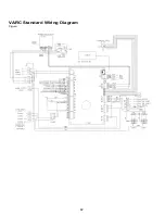
Страница 69: ...67 VARC Standard Wiring Diagram Figure...
Страница 70: ...68 NOTES...
Страница 71: ...69 NOTES...


