(36)
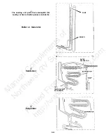
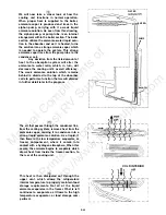
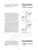
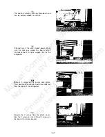
and onto the orifice and burner assembly.
Remember that except
for the connection
piece,
all fittings are O-ring sealed.
Whenever the
system is separated the O-rings must be
replaced.
ORIFICE & BURNER
ASSEMBLY
(37)
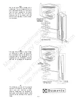
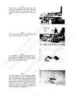
To diagnose the gas system, connect a
manometer to the test point. With the
thermostat on maximum you must have 11
inches water column pressure at this point.
If
you have 11 inches pressure, your problem
Is to the right of the test point. If you do not
have 11 inches water column pressure, the
problem Is to the left.
(38)
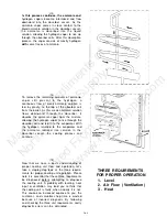
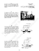
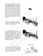
Let’s take a closer look at the gas thermostat.
In this drawing we will review how a thermostat
functions. When the thermostat is working
properly, the manometer will read line pressure
when set at maximum and the refrigerator is
trying to cool. From this drawing you can see
the gas flow when the refrigerator is trying to
cool. The gas flows through the thermostat at
line pressure without restriction. The valve is
(39)
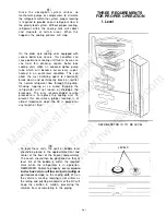
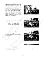
The valve is now closed and the gas must flow
through the by-pass screw; the gas is now
diverted through the by-pass screw, which
regulates the size of the low flame. This
condition can only exist when the refrigerator is
cold or the thermostat is set to minimum or off.
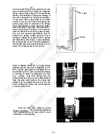
If the sensing tube has lost its pressure, even
with the thermostat set on maximum, you will
have only low flame.
DIAL SHAFT
open at this time.
VALVE
DIAL SHAFT
SCREW CLOSED VALVE
D-6-13
Manual
Compliments
of
Northwest
RV
Supply
Printed
From
http://www.nwrvsupply.com

