SuperSigma2 AM PMS
–
V1.5.6 17-1-2020
Page 89 (97)
©2019 DMC GmbH Herten Germany
12
Diagnostics
12.1
Error Codes
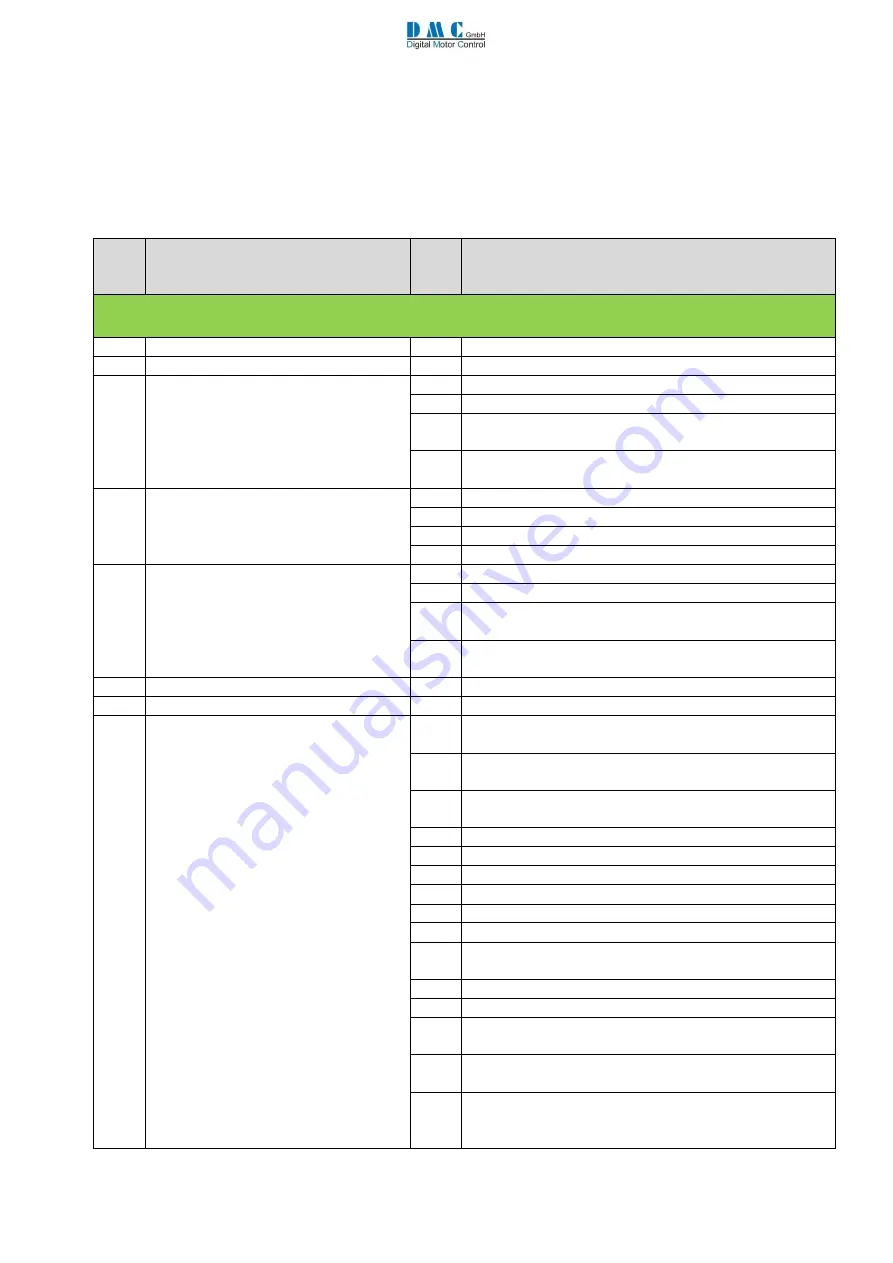
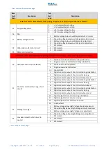
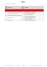
The following tables describe all the error codes that the controller will display. The presence of an error can be detected
by means of a red led flashing on controller (number of flashes correspond to base error code) and investigated in
.
The error codes are divided in four different categories, based upon the severity of the faults.
Base
fault
Code
Description
Sub
fault
code
Description
Controller warning faults - Reduces only performance - Fault will reset itself (if possible)
0
No error
-
-
1
N/A
-
2
Voltage getting low
1
Battery voltage below absolute minimum
2
Capacitor voltage below absolute minimum
3
Battery voltage below LV cut back adjustment (drive cut
back active)
4
Capacitor voltage below LV cut off adjustment (drive cut
back active)
3
Inhibit drive/ BDI Cut / BLC via can
1
BDI Cut out (Battery below BDI cut Level)
2
Pump inhibit input active (Only Pump Software)
3
BCL via CAN message time out
4
BCL via CAN message toggle security bit fail
4
Voltage getting high
1
Battery voltage above absolute minimum
2
Capacitor voltage above absolute minimum
3
Battery voltage above High Voltage cut back adjustment
(brake cut back active)
4
Capacitor voltage above High Voltage cut back adjustment
(brake cut back active)
5
Motor temperature high
-
6
Controller temperature high
-
7
Adjustment out of range
1
Master does not share the line contactor but any one of
the slave does
2
Master shares the line contactor but one of the requested
slave doesn’t
3
A slave node number larger than last sharing node also
share the line contactor
4
WigWag is enabled but walkie is not
5
inching and walkie are both enabled
6
dual motor with speed control mode
7
shared LC and Control Via CAN HMI both active
8
Inching and Control Via CAN HMI both active
9
Walkie and Control Via CAN HMI both active
10
Control Via CAN HMI enabled and CAN node number set
as master
11
Hill hold Enabled and Torque control enabled
12
---
13
CAN control type options are active but Control Via CAN
HMI is not enabled.
14
Can Node ID via digital input enabled but control but
Control Via CAN HMI is not enabled.
15
means Shared Line Contactor HMI option is activated
(“ShareLC”>=2) on but not control via CAN HMI active
(CANMsgs>=4). Solution set CANMsgs < 4.
Errors continue at next page…


