SuperSigma2 AM PMS
–
V1.5.6 17-1-2020
Page 64 (97)
©2019 DMC GmbH Herten Germany
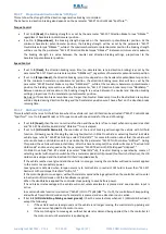
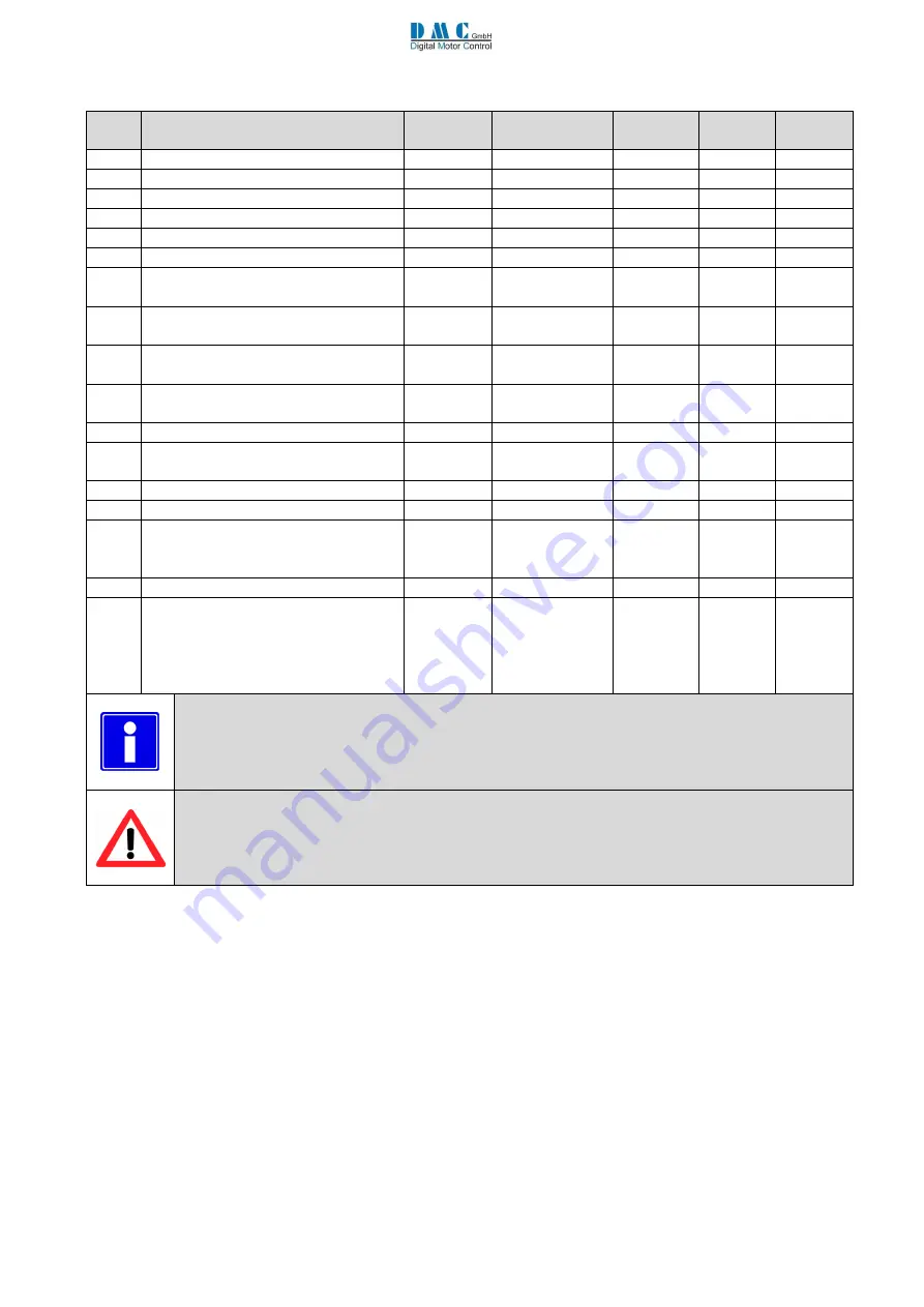
6.2
Menu 4 “PMS
Motor Auto Tuning
”
Cal.
Ref.
Parameter (Param.)
Calibrator
text
Min. adjust
Max.
adjust
Step
size
Default
1
Number of motor poles
Nmotpole
2
48
2
8
2
Sensor technology
1)
SensTech
0
2
1
0
3
Sensor supply voltage
SenSuppV
0
1
1
0
4
Number of sensor poles
NsnsPole
2
48
2
2
5
Reverse sensor reading
SpdRever
0
1
1
0
6
Reverse motor direction
MotorRev
0
1
1
0
7
*
Battery Voltage
BattV AT
12. 0 V
Units
Umaxnom
1V
24V
8
**
RMS motor current For tuning
I for AT
1 Arms
Units Imax
Arms
1 Arms
½ max
current
9
*
Maximum RMS motor current
Imotmax
1 Arms
Units Imax
Arms
1 Arms
Max
current
10
*
Back e.m.f. constant (KeV)
K emf
0.0 V/krpm
144.0
V/krpm
0.1
V/krpm
10.0
V/krpm
11
*
Motor phase to phase inductance
L ph-ph
0 μH
3200.
0 μH
1 μH
12
0 μH
12
*
Maximum demagnetizing (Field
weakening) current
I demag
1 Arms
(disabled)
600 Arms
1 Arms
1 Arms
13
*
Maximum Motor Frequency
Fmotmax
0.0 Hz
700.0 Hz
0.1 Hz
100.0 Hz
14
Start Auto-tuning
AutoTune
0
1
1
0
15
Recalculation after changing one of
the adjustments of this menu marked
with one star
*
Recalcul
0
1
1
0
16
Sin/Cos Sensor Delay Angle at 100 Hz
SensDel
0,0 deg
15,0 deg
0,1 deg
3,6 deg
17
Auto Tuning Type:
0= Standard auto tuning (position
sensor tuning)
1= Full autotuning (position
Inductance and Ke mesurment)
ATuneType
0
1
1
0
(
*
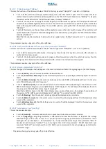
) If a parameter with one star is changed, recalculation is required.
Recalculation is performed after setting the recalculation parameter to 1 and recycling the key.
(7
**
) The
nominal current for autotuning “Inom” have to be set not higher th
an 30-40% of motor
continuous current. Higher values can overheat and or damage the motor.
(
**
)
Changes to parameters with two stars are only considered when performing auto tuning after
recycling the key !
Note
1)
: sensorless options available on request. Refer to DMC.
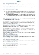
M4-1
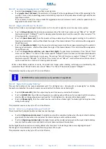
Number of motor poles
“NmotPole”
Number of motor poles.
M4-2
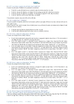
Sensor technology
“SensType”
•
If set to
0
(Analog Sine Cosine)
, an analog sine-cosine sensor must be connected. The sensor has to give two
signals: one sine wave and one cosine wave per revolution of the motor shaft. The signal must be between 0 and
5V and have an offset around 2.5 V.
•
If set to
1
(Hall sensor)
, a three channel position hall sensor must be connected. Selection to 1 is available on
request. Refer to DMC for details.
•
If set to
2
(Sensorless)
, no sensor is required. This Selection is available on request. Refer to DMC for details.

