HYDRAULIC DRIVE INSTALLATION
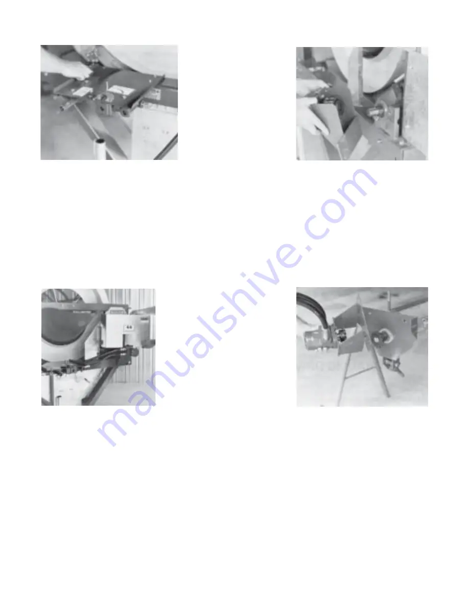
Photo 102
Photo 103
Photo 104
Photo 105
Step A.
Bolt hydraulic control panel to front assembly, using four 1/4” x 3/4” hex bolts,
lock washers and hex nuts. See Photo 102.
Step B.
Remove hex nut and washer from 3/8” x 5-1/2” hex bolt at top left front brace
extension. Next, install 1/4” x 1” square key into keyway of the drive shaft.
Slide sprocket of hydraulic motor and chain coupler assembly onto the
drive shaft and align coupling unit. Fasten to cleaner, using 3/8” x 5-1/2” bolt,
and one 3/8” x 1-1/4” hex bolt, two SAE flat washers, lock washers and hex
nuts. Tighten bolts & set screws in sprocket. See Photo 103.
Step C.
Hydraulic Motor Shield: Loosen two 1/4” x 3/4” self-tapping screws holding
small back panel shield. Slide back panel shield to outside. Hook hydraulic
shield locating pins into upper shield holding bracket, slide panel shield against
hydraulic motor shield. Remove shield. Retighten self-tapping screws holding back
panel. Hook hydraulic motor shield on to cleaner and latch into position.
See Photo 104.
Step D.
Auger: Install 1/4” x 1” square key into auger shaft, slide #50 x 14 tooth sprocket on
auger shaft with hub to inside. SCREWS ON SPROCKET SHOULD REMAIN
LOOSE. See Photo 105. Bolt hydraulic motor with mount to face of auger head
using two 3/8” x 3/4” carriage bolts, lock washers and hex nuts. Align sprocket and
tighten bolts. Position sprocket on auger shaft so the two sprockets are approximately
5/16” apart. Finish by installing #50 roller chain coupler.
Step E.
Install coupler cover shields using four 1/4” x 3/4” self-tap screws. See Photo 106.
32
Содержание Hi Cap 54
Страница 1: ...OWNER S MANUAL Hi Cap 54 Grain Cleaner PNEG 1147 PNEG 1147 Date 3 1 02...
Страница 43: ...MODEL 54 HI CAP DRUM 34...
Страница 45: ...36...
Страница 46: ...37...
Страница 47: ...38...
Страница 48: ...39...
Страница 53: ...44...
Страница 55: ...46...
Страница 57: ...48...
Страница 58: ...49...


