17
©
Dinel, s.r.o. CLM–70
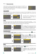
1. Bring the measured medium to the minimum capacity. In the
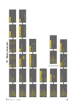
BASIC SETTINGS – MIN CA-
PACITY
menu, the value of electrical capacity measured by the level meter in real time is
displayed in the upper right corner under the sign “
ACTUAL CAPACITY
”. This value must be
copied to the
CAPACITY
line. The value which is shown on the display at this minimum capac
-
ity is entered in the
DISPLAY
line. The
OUTPUT
line is not editable and displays the value of
an output variable at the minimum capacity.
2. Bring the measured medium to the maximum capacity. In the
BASIC SETTINGS – MAX CA-
PACITY
menu, the value of electrical capacity measured by the level meter in the real time is
displayed in the upper right corner under the sign “
ACTUAL CAPACITY
”. This value must be
copied to the
CAPACITY
line. The value which is shown on the display at this maximum ca
-
pacity is entered in the
DISPLAY
line. The
OUTPUT
line is not editable and displays the value
of an output variable at the maximum capacity. The conversion to the shown value on the
display and the output (current) is always linear depending on the capacity to be measured.
3. In the
BASIC SETTINGS – UNITS
menu, the required units for display on the main screen of
the meter display are set in the
DISPLAY
line. The
CAPACITY
line is not editable and indicates
in which units the level meter measures the capacity.
4.
The time constant of the output variable filter is set in the
BASIC SETTING – DAMPING
menu.
B) THE SETTING METHOD AT ANY POINT WITHIN THE RANGE
(if the tank cannot be completely
emptied or flooded with a medium)
1.
Flood the tank to a known level H
1
(e.g. 15%). In the
SERVICE – CAPACITY
menu item, the
capacity at this known flooding (15%) can be found. This capacity is noted down and denoted
as C
1
(e.g. 35 pF).
2.
Flood the tank to another known level H
2
(e.g. 78%). In the
SERVICE – CAPACITY
menu
item, the capacity at this known flooding (78%) can be found. This capacity is noted down
and denoted as C
2
(e.g. 126 pF).
3. The capacities at the limit points of the measuring range can be calculated using the follow
-
ing formulas.
For capacity at the lower limit point of the measuring range:
C
MIN
= C
1
– H
1
∙ (C
2
– C
1
) / (H
2
– H
1
)
Example: C
MIN
= 35 – 15 ∙ (126 – 35) / (78 – 15) = 13.33 pF
For capacity at the upper limit point of the measuring range:
C
MAX
= C
MIN
+ 100 ∙ (C
2
– C
1
) / (H
2
– H
1
)
Example: C
MAX
= 13.33 + 100 ∙ (126 – 35) / (78 – 15) = 157.77 pF
4. The calculated value of C
MIN
is to be entered into the meter’s
BASIC SETTINGS – MINIMUM
CAPACITY
menu
in the CAPACITY line
. The value to be displayed at the minimum capacity
is entered in the
DISPLAY
line. The
OUTPUT
line is not editable and displays the value of an
output variable at
the minimum capacity
.
5. The calculated value of C
MAX
is to be entered into the meter’s
BASIC SETTINGS – MAXIMUM
CAPACITY
menu
in the CAPACITY line
. The value to be displayed at the maximum level is
entered in the
DISPLAY
line. The
OUTPUT
line is not editable and displays the value of an
output variable at the maximum capacity. The conversion to the display value and the output
quantity (current) is always linear depending on the capacity to be measured.
6. In the
BASIC SETTINGS – UNITS
menu, the required units for display on the main screen of
the meter display are set in the
DISPLAY
line. The
CAPACITY
line is not editable and indicates
in which units the level meter measures the capacity.
7.
The time constant of the output variable filter is set in the
BASIC SETTING – DAMPING
menu.
Содержание CLM-70
Страница 2: ......

