
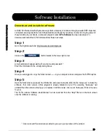

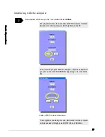


Wire the Amplifier
based on the diagram shown below.
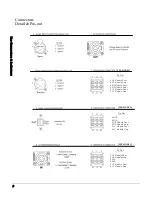
Consult Speaker Wire Connector Details and Pin-out on page 10.
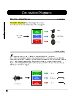
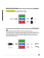
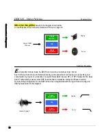
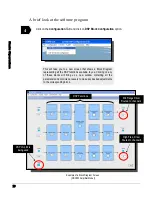
ach amplifier module inside the DDC552 is routed to an individual logic channel.
Each of these channels is a dedicated processing unit responsible for achieving a very specific sound
characteristic by means of a collection of powerful filters which include: HP, LP, BP, Parametric EQ, Bass
Shelf, Treble Shelf as well as other DSP functions like Compression, Delay and Phase Inversion.
By default the Configuration for the DDC520 has been programmed with the logic channel routing and
filtering represented in this diagram.
Input XLR
(Mono)
Highs
Lows
DDC520 – Driver Wiring
Hard-wiring
250 W
Amplifier
N/A
500 W
Amplifier
Software Routing
Audio Signal
Highs
Lows
Logic
channel 6
N/A
Logic
channel 6
E
Содержание DDC520
Страница 1: ... DDC 500 Series ...
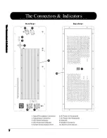
Страница 7: ... The Connectors Indicators Front Panel Back Panel ...
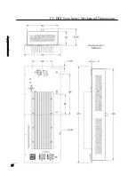
Страница 27: ... IV DDC5xxx Series Mechanical Dimensions ...


