background image


page 81

Digital Projection HIGHlite 740 Series

Reference Guide

CHOOSING A LENS

Rev I February 2015

Basic calculation

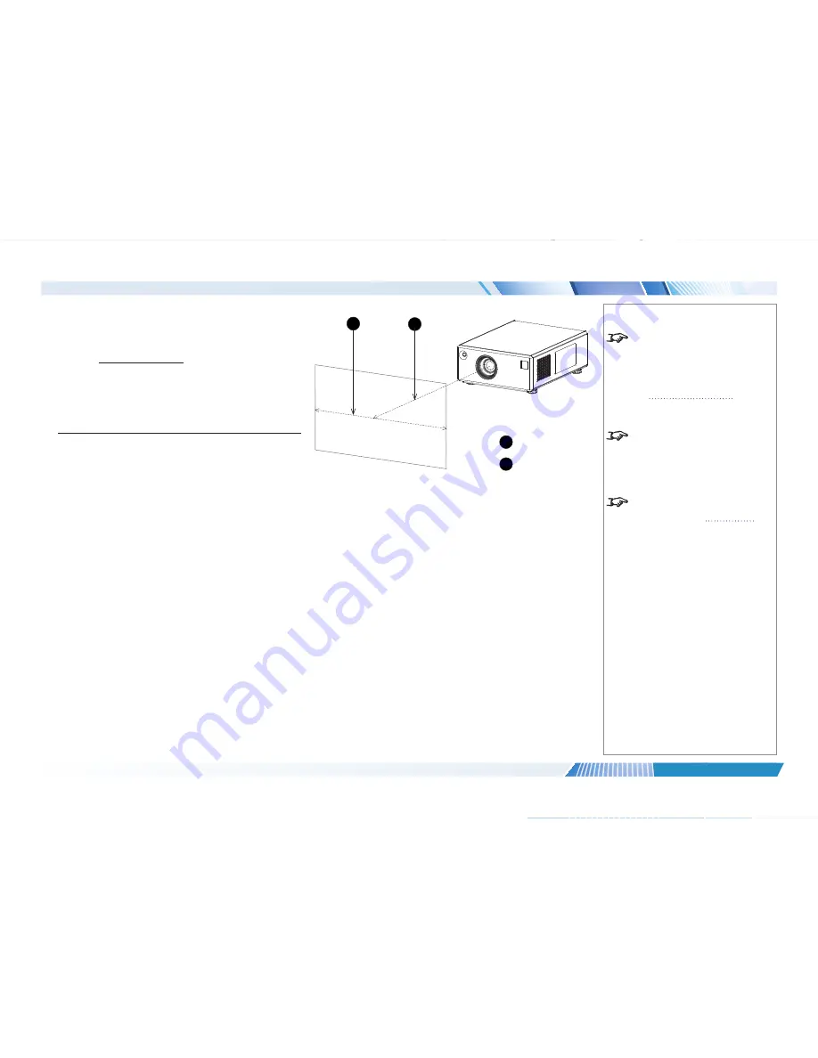
Identify the required lens by calculating the 

throw ratio

.

throw ratio

 is the ratio of the throw distance to the screen width:

Throw distance

Screen width

Throw ratio =

1.  Use the formula above to obtain the required throw ratio.
2.  Match the throw ratio with a lens from the table below:

Throw ratios

Throw distance range

0.77 : 1 fixed lens

1.3 - 2.5 m (4.3 - 8.2 ft)

1.16 : 1 fixed lens

1.4 - 6.2 m (4.6 - 20.3 ft)

1.45 - 1.74 : 1 zoom lens

1.8 - 9.3 m (5.9 - 30.5 ft)

1.74 - 2.17 : 1 zoom lens

2.2 - 11.8 m (7.2 - 38.7 ft)

2.17 - 2.90 : 1 zoom lens

2.7 - 15.4 m (8.9 - 50.5 ft)

2.90 - 4.34 : 1 zoom lens

3.6 - 22.5 m (11.8 - 73.8 ft)

4.34 - 6.76 : 1 zoom lens

5.5 - 35 m (18 - 115 ft)

3.  Ensure the required throw distance is within the range covered by the lens.

Notes

  The basic calculation on this page 

does not take into consideration 

DMD™ and image size, which could 

affect the throw ratio. For a more 

complex and realistic calculation, 

see 

Full lens calculation

 in this 

section.

  When calculating the throw ratio, be 

sure to use identical measurement 

units for both the throw distance and 

the screen width.

  For information about individual lens 

part numbers, see 

Appendix A

 at 

the end of this document.

1

2

1

Screen width

2

Throw distance

Содержание HIGHlite 740 1080p

Страница 1: ...Rev I February 2015 HIGHlite 740 Series High Brightness Digital Video Projector 4INSTALLATION AND QUICK START GUIDE 4CONNECTION GUIDE 4OPERATING GUIDE 4REFERENCE GUIDE 114 751I ...

Страница 2: ...ess the instructions are closely followed ELECTRICAL WARNING this symbol indicates that there is a danger of electrical shock unless the instructions are closely followed NOTE this symbol indicates that there is some important information that you should read Product revision Because we at Digital Projection continually strive to improve our products we may change specifications and designs and ad...

Страница 3: ...og inputs Control of most aspects of the projector s operation via LAN and RS232 Support for a number of aspect ratios and screen sizes Non linear warp adjustment by moving points on an interpolated grid Ceiling mount and rear screen installation options Simultaneous display of two sources via Picture In Picture Long lamp life Motorised lens mount A serial number is located on the back of the proj...

Страница 4: ...ns 13 OPERATING THE PROJECTOR 14 Switching the projector on 14 Switching the projector off 14 Selecting an input signal or test pattern 15 Input signal 15 Test pattern 15 Adjusting the lens 16 Zoom 16 Focus 16 Shift 16 Adjusting the image 17 Orientation 17 Keystone 17 Picture 17 CONNECTION GUIDE 19 SIGNAL INPUTS AND OUTPUTS 21 EDID on the DVI and VGA inputs 23 Using HDMI DVI switchers with the pro...

Страница 5: ...ine 39 Edge Blend menu 45 Overview 45 Array H Position and V Position 46 S Curve Value 47 Blending 49 Segmentation 50 Blend Width 52 Black Level Uplift 52 Reduce Black Level Uplift Width 53 Blending images from multiple projectors 56 Before you start 56 Edge Blend procedure 57 PIP menu 65 Lamps menu 66 Setup menu 67 Reset Default Settings 67 Input Configuration 68 Network 69 On Screen Display 70 S...

Страница 6: ...ED 97 Aspect ratio examples for DMD resolution 1080p 98 Aspect ratio examples for DMD resolution WUXGA 101 Aspect ratio example TheaterScope 104 FRAME RATES AND PULLDOWNS EXPLAINED 105 Interlaced and progressive scan 105 Frame rates of image sources 105 Pulldowns conversion into destination formats 106 2 3 normal pulldown 106 2 3 3 2 advanced pulldown 107 APPENDIX A LENS PART NUMBERS 108 APPENDIX ...

Страница 7: ...onent 132 Input 8 CVBS 132 Control connections 133 Wired remote control 133 RS232 134 LAN connection 134 APPENDIX F GLOSSARY OF TERMS 135 TECHNICAL SPECIFICATIONS 144 Models 144 Inputs and outputs 145 Bandwidth 145 Remote control and keypad 145 Automation control 145 Color temperature 145 Lamps 146 Lenses 146 Lens mount 146 Mechanical mounting 146 Orientation 146 Electrical and physical specificat...

Страница 8: ...Digital Projection HIGHlite 740 Series This page is intentionally left blank ...

Страница 9: ...Rev I February 2015 HIGHlite 740 Series High Brightness Digital Video Projector INSTALLATION AND QUICK START GUIDE 4 ...

Страница 10: ...ote control 7 Infrared reception 9 Remote control troubleshooting 10 Positioning The Screen And Projector 11 Changing The Lens 12 Inserting a new lens 12 Removing the lens 13 Operating The Projector 14 Switching the projector on 14 Switching the projector off 14 Selecting an input signal or test pattern 15 Input signal 15 Test pattern 15 Adjusting the lens 16 Zoom 16 Focus 16 Shift 16 Adjusting th...

Страница 11: ...tion territory will be supplied with the projector Remote control 105 023 4x AAA cells Power cable United Kingdom 112 000 User Manual on disc 115 759 Important Information 114 750 Power cable Europe 112 001 Power cable North America 112 002 Projector VG A HD MI DV I 3G SD I CV BS 1 SV ID EO CL OS E 1 2 3 4 CO MP CV BS 2 5 6 7 8 9 0 10 MA IN SU B DU AL HD T O FF O N A LT R O LL PI TC H YA W FO C U ...

Страница 12: ...le lock up push the mains connector in firmly and push the lock down to secure the cable 1 AC mains inlet with cable lock Rear view of the projector 1 Notes Use only the power cable provided Ensure that the power outlet includes a ground connection as this equipment MUST be earthed Handle the power cable carefully and avoid sharp bends Do not use a damaged power cable ...

Страница 13: ...ECTOR OVERVIEW Rev I February 2015 Projector Overview Front and rear views 1 Front infrared window 2 Lens 3 Air outlet 4 Adjustable feet 5 Control panel 6 Rear infrared window 7 Connection panel 8 Power switch and power connection 9 Air inlet 9 5 8 7 6 Rear view Front view 1 2 4 3 Notes ...

Страница 14: ...osed On green The shutter is open 3 Error indicator Behavior Meaning On red Voltage Error Flashing Temperature Error 4 Lamp 1 and Lamp 2 indicators Behavior Meaning On green The lamp is switched on 100 On amber The lamp is switched on 80 99 Flashing green The lamp is warming up Flashing amber The lamp is cooling down Flashing red Lamp Error 5 Infrared indicator Behavior Meaning Flashing blue The p...

Страница 15: ...rows confirm your choice with OK 7 Input selection Select input source 8 Image adjustment Adjust brightness contrast and gamma Press this button while holding the ALT button down to switch red green and blue channels on and off 9 Remote control backlight ON OFF Make the remote control buttons glow in the dark or switch this feature off continues on next page Notes Only the controls shown highlight...

Страница 16: ...t up an address to match the IR address of a projector Notes Only the controls shown highlighted are used on this projector For more information about IR addresses see Setting up an IR address in the Operating Guide VGA HDMI DVI 3GSDI CVBS1 SVIDEO CLOSE 1 2 3 4 COMP CVBS2 5 6 7 8 9 0 10 MAIN SUB DUAL AUX OFF ON ALT ROLL PITCH YAW FOCUS CAL SHIFT ZOOM EYE SWAP MAIN PIP SWAP BRI CON GAMMA 3D ON OFF ...

Страница 17: ...e angle of acceptance is 40 Make sure that the remote control is within the angle of acceptance when trying to control the projector Notes Infrared reception is confirmed by the blue IR LED flashing on the control panel The infrared receivers are disabled when a remote control is connected via a cable For more information see Control Connections in the Connection Guide 40 40 Infrared reception ...

Страница 18: ... the projector control panel respond when a remote control button is pressed When a button is pressed on the remote control the infrared indicator 2 on the control panel should flash blue If this does not happen Check that the angle of acceptance is met Check that the projector address matches the remote control address If none of the above fixes the problem it might be time to replace the battery...

Страница 19: ...for table mounting and the fixing holes for ceiling mounting 1 Four adjustable feet 2 Six M6 holes for ceiling mount The screws should not penetrate more than 15 mm 0 6 in into the body of the projector Notes Always allow the projector to cool for 5 minutes before disconnecting the power or moving the projector Ensure that there is at least 30 cm 12 in of space between the ventilation outlets and ...

Страница 20: ...ion the projector can be tilted up to 12º 360º Pitch 1 12º Roll air outlet downward 1 1 90º Roll air outlet upward 1 Notes Always allow the projector to cool for five minutes before disconnecting the power or moving the projector Ensure that there is at least 30 cm 12 in of space between the ventilation inlets and outlets and any wall and 10 cm 4 in on all other sides Do not stack more than three ...

Страница 21: ... lines up with the socket 4 on the right of the lens aperture 5 Push the lens in firmly as far as it will go 6 Rotate the lens clockwise as far as it will go 7 Replace the front cover and secure it with the six screws Notes Before changing the lens always make sure the projector is switched off and fully disconnected from its power supply Always allow the lamp to cool for 5 minutes before disconne...

Страница 22: ... 5 Pull the lens forward to remove it from the lens aperture 2 1 3 Notes Before changing the lens always make sure the projector is switched off and fully disconnected from its power supply Always allow the lamp to cool for 5 minutes before disconnecting the power moving the projector When changing the lens avoid using excessive force as this may damage the equipment Avoid touching the surface of ...

Страница 23: ... to switch the projector ON The power indicator on the control panel will show green the lamp will light and the shutter will open Switching the projector off 1 Press OFF on the remote control or the control panel and hold for three seconds The power indicator on the control panel will show amber the lamp will go out and the cooling fans will run for a short time until the projector enters STANDBY...

Страница 24: ... the Input Selection menu using the UP and DOWN arrow buttons then press OK Test pattern To display a test pattern 1 Open the OSD by pressing MENU 2 Select Test Pattern from the Input Selection menu using the UP and DOWN arrow buttons then press OK 3 Select a pattern from the Test Pattern menu using the UP and DOWN arrow buttons then press OK 4 Close the OSD by pressing MENU again Notes For full d...

Страница 25: ...cus When the adjustment is finished press EXIT Shift Press SHIFT then use the UP DOWN LEFT and RIGHT arrow buttons on the keypad or remote control to adjust the position of the image on the screen When the adjustment is finished press EXIT Notes When any of the three lens adjustment buttons is pressed the blue Transmit indicator on the remote control will light for 10 seconds After 10 seconds if n...

Страница 26: ...tness and Contrast can be set from the Image menu You can also set Brightness Contrast or Gamma by pressing BRI CON or GAMMA on the remote control Notes Main Menu Setup From the audience s point of view lens shift always moves the image in the same direction regardless of projector orientation For example SHIFT UP always moves the image toward the ceiling and SHIFT LEFT always moves the image to t...

Страница 27: ...Digital Projection HIGHlite 740 Series Installation and Quick Start Guide This page is intentionally left blank ...

Страница 28: ...Rev I February 2015 HIGHlite 740 Series High Brightness Digital Video Projector CONNECTION GUIDE 4 ...

Страница 29: ...tion Guide IN THIS GUIDE Rev I February 2015 IN THIS GUIDE Signal Inputs And Outputs 21 EDID on the DVI and VGA inputs 23 Using HDMI DVI switchers with the projector 23 Control Connections 24 LAN connection examples 25 RS232 connection example 26 ...

Страница 30: ...as a DVI I connector which can receive either analog DVI A or digital DVI D signal from a compatible source Set DVI I Port in the Setup Input Configuration menu to choose between Analog and Digital 3 HDMI Receives digital signal from HDMI compliant devices The audio from the HDMI source is available on the SPDIF output 4 S PDIF This is a digital output Compatible audio sample packets on the HDMI i...

Страница 31: ...GA Receives analog signal from a computer When using this input it is best to use a fully wired VGA cable to connect the source to the projector This will allow the source to determine the projector s capabilities via DDC and show an optimized image Such cables can be identified as they have a blue connector shell Use Auto Setup in the Image VGA Setup menu 9 Composite 2 CVBS 2 Uses an RCA phono co...

Страница 32: ...ain Using HDMI DVI switchers with the projector When using an HDMI DVI source switcher with the projector it is important to set the switcher so that it passes the projector EDID through to the source devices If this is not done the projector may not be able to lock to the source or display the source correctly as its video output timings may not be compatible with those of the projector Sometimes...

Страница 33: ... to connect to a network hub 4 Wired remote output To synchronize the control of multiple projectors connect the wired remote output of one projector to the wired remote input of another Wired remote input If infrared signals from the remote control cannot reach the projector due to excessive distance or obstructions such as walls or cabinet doors you can connect an external IR repeater to the rem...

Страница 34: ...TIONS Rev I February 2015 LAN connection examples The projector s features can be controlled via a LAN connection using a standard internet browser package Back panel 1 Notes Hub or LAN Computer Projector Projector Un crossed LAN cables Projector Computer Crossed LAN cable 1 LAN ...

Страница 35: ... Digital Projection HIGHlite 740 Series Connection Guide CONTROL CONNECTIONS Rev I February 2015 RS232 connection example Notes Projector Computer Null modem cable Back panel with control connections 1 1 RS232 ...

Страница 36: ...Rev I February 2015 HIGHlite 740 Series High Brightness Digital Video Projector OPERATING GUIDE 4 ...

Страница 37: ...and Gain sliders 36 Geometry menu 37 Aspect Ratio 37 Overscan 37 Size Position 38 Geometry Engine 39 Edge Blend menu 45 Overview 45 Array H Position and V Position 46 S Curve Value 47 Blending 49 Segmentation 50 Blend Width 52 Black Level Uplift 52 Reduce Black Level Uplift Width 53 Blending images from multiple projectors 56 Before you start 56 Edge Blend procedure 57 PIP menu 65 Lamps menu 66 Se...

Страница 38: ...ay OSD press MENU Menus and sub menus To open a sub menu select it using the UP and DOWN arrow buttons then press OK To return to the previous menu press EXIT Notes Some menu items may not be available due to settings in other menus These will be grayed out on the actual menu When a globe icon appears next to a setting the setting affects all sources and all inputs otherwise only the current input...

Страница 39: ...the list using the UP and DOWN arrow buttons 3 Press OK again to select the highlighted item or press EXIT to exit without changing Notes Some menu items may not be available due to settings in other menus These will be grayed out on the actual menu When a globe icon appears next to a setting the setting affects all sources and all inputs otherwise only the current input source will be affected if...

Страница 40: ...s To use a command press OK In the example below press OK to confirm or press EXIT to cancel Notes Some menu items may not be available due to settings in other menus These will be grayed out on the actual menu When a globe icon appears next to a setting the setting affects all sources and all inputs otherwise only the current input source will be affected if you change the setting ...

Страница 41: ...OK 2 Use the LEFT and RIGHT arrow buttons to move the green highlight to the digit or character which is to be changed then use UP and DOWN to adjust it 3 Use the LEFT and RIGHT arrow buttons to select the next digit or character 4 Press OK to accept the new value or press EXIT to exit without changing Notes Some menu items may not be available due to settings in other menus These will be grayed o...

Страница 42: ... and vice versa Lamps Select lamp configuration and adjust lamp power Setup Adjust Input Configuration Network On Screen Display and System settings Information View your current configuration Notes Main Menu You can also select an input source by pressing the following buttons on the remote control 1 for VGA 2 for HDMI 1 3 for DVI 1 4 for 3G SDI 5 for CVBS 1 6 for S Video 7 for Component 8 for CV...

Страница 43: ...e image is correctly focused select Focus Stop and then press OK Center Lens To center the lens select Center Lens and press OK Nudge To position the image correctly on the screen use the Nudge controls Notes Main Menu Lens You can also move the lens focus and zoom using the keypad or the remote Press SHIFT followed by an arrow button to shift the lens up down left and right Press FOCUS followed b...

Страница 44: ...ial temporal noise only applicable to standard definition video signals Mosquito NR a noise reduction filter which reduces block artifacts only applicable to standard definition video signals Cross Color Suppression a filter which reduces luminance to chrominance crosstalk on Composite Video signals The crosstalk appears as a rainbow pattern in regions of fine detail VGA Setup Use Auto Setup to al...

Страница 45: ...mage Choose HDTV for high definition standards and SDTV for standard definition standards A value between 3200K and 9000K selects the relevant color temperature You can upload your own gamut using the Projector Manager software and then select it from the User 1 and User 2 settings Black Level and Gain sliders Set the sliders as required Notes Main Menu Color ...

Страница 46: ...orphic aspect ratio Overscan Set this slider to compensate for noisy or badly defined image edges Image with noisy edges Overscanned image Notes Main Menu Geometry An anamorphic lens optional accessory is used with the TheaterScope setting to ensure that for a 2 35 1 image the maximum area of the DMD is used giving maximum image brightness For examples of how the different aspect ratios affect scr...

Страница 47: ...case these settings will be applied to all signals on all inputs or Per Mode in which case these settings will be applied only to the current input signal Set the H Position and V Position sliders as required Set H Size and V Size When Aspect Lock is set to On the V Size slider is disabled Select Reset and press OK to reset all the sliders Notes Main Menu Geometry Size Position ...

Страница 48: ... correct for any distortion caused by the projector being in a different horizontal or vertical plane to the screen 1 The projector is positioned at an angle 2 The resulting image is distorted 3 The image is corrected when Keystone is applied Notes Main Menu Geometry Some items on this menu may be unavailable depending on the Geometry Engine setting If possible position the projector facing the sc...

Страница 49: ...rrow button 3 Projector high The projector is positioned above the screen at a downward angle To correct apply a negative V Keystone value using the LEFT arrow button 4 Projector low The projector is positioned below the screen at an upward angle To correct apply a positive V Keystone value using the RIGHT arrow button 5 Projector straight The projector is directly opposite the screen at a right a...

Страница 50: ...Geometry Engine is set to Keystone or Rotation Set the slider to correct for any distortion caused by the screen being concave or convex Notes Main Menu Geometry Some items on this menu may be unavailable depending on the Geometry Engine setting If possible position the projector facing the screen at a right angle to avoid geometry corrections Pincushion Barrel ...

Страница 51: ...ion The DMD is not rotated 2 Area outside DMD The corners of the rotated image leave the DMD and appear cropped 3 Angle of rotation The angle equals the Rotation setting In this example the angle is 25 therefore Rotation 25 Notes Main Menu Geometry Some items on this menu may be unavailable depending on the Geometry Engine setting If possible position the projector facing the screen at a right ang...

Страница 52: ...you can select from the drop down list 1 Distorted image The image is projected on an uneven surface 2 Warp map The map mirrors the surface raised areas on the surface correspond to hollow areas on the map and vice versa 3 Corrected image With the warp map applied the projector compensates for the surface and the projected image appears undistorted Notes Main Menu Geometry Some items on this menu ...

Страница 53: ...ROJECTOR Rev I February 2015 Geometry Engine continued Cornerstone If Cornerstone is selected from the main Geometry page you can use the sliders to stretch the image from each of the four corners Notes Main Menu Geometry Cornerstone Upper Right X and Upper Right Y correction ...

Страница 54: ...age Image brightness changes from one point to another within the same blended region If the same level of black level uplift is applied throughout the blended region the overlapping edges may still be visible on the screen Therefore brightness in these areas is decreased gradually using an s curve factor S Curve Value is used to control the steepness of the decrease Notes Main Menu Edge Blend Thi...

Страница 55: ...position in the array The settings for the third projector in the second row 1 are Array H Position 2 Array V Position 1 Notes Main Menu Edge Blend This menu is available only when Setup System Configuration is set to Edge Blend None of the other items in this menu are available until either the Array Width or the Array Height setting is greater than 1 The position numbering starts from zero so th...

Страница 56: ...epness of this decrease Notes Main Menu Edge Blend This menu is available only when Setup System Configuration is set to Edge Blend None of the other items in this menu are available until either the Array Width or the Array Height setting is greater than 1 For a detailed step by step description of the edge blend process see Blending images from multiple projectors further in this section 1 S Cur...

Страница 57: ...ht from each source in the overlapping region the total amount of light in the region would remain constant as shown in Fig 2 Fig 1 Overlapping edges without S Curve Fig 2 Applying S Curve to overlapping edges Notes Main Menu Edge Blend This menu is available only when Setup System Configuration is set to Edge Blend None of the other items in this menu are available until either the Array Width or...

Страница 58: ...kes the overlaps more visible and helps adjust the physical position of the projectors in the array The size of the align pattern is controlled by the Blend Width group of settings Notes Main Menu Edge Blend This menu is available only when Setup System Configuration is set to Edge Blend None of the other items in this menu are available until either the Array Width or the Array Height setting is ...

Страница 59: ...r will display its own segment only Set to Off if you have external software that handles segmentation Notes Main Menu Edge Blend This menu is available only when Setup System Configuration is set to Edge Blend None of the other items in this menu are available until either the Array Width or the Array Height setting is greater than 1 For a detailed step by step description of the edge blend proce...

Страница 60: ...ge source DVD player Blu ray computer etc 2 Distribution Amplifier Sends the source image to all projectors in the array 3 Array Segmentation is on Each projector displays a segment Notes Main Menu Edge Blend For a detailed step by step description of the edge blend process see Blending images from multiple projectors further in this section 2 3 1 ...

Страница 61: ...es on all sides 5 Unblended Region This region is not overlapped Black level should be raised by the maximum overlap occurring within the segment therefore Black Level Uplift should be x4 6 Upper Middle This section of the image is overlapped by two projectors therefore the correct amount of Black Level Uplift should be x2 7 Upper Right This part of the image is overlapped by four projectors there...

Страница 62: ...ges where the black level uplift region of one projector overlaps the pond of mirrors of the other To remove the artifacts you need to slightly reduce the size of the black level uplift region of each projector so it does not overlap the pond of mirrors of the other projector 1 2 3 4 Notes Main Menu Edge Blend Reduce Black Level Uplift Width To apply the settings in this menu use the Apply Uplift ...

Страница 63: ...ojector It can be eliminated if the black level uplift width of this projector is reduced 3 Blend region The area in the middle of the array where the two images overlap Black level uplift has not been applied here 4 Artifact right This artifact is caused by this projector s pond of mirrors overlapping the black level uplift region of the other projector It can be eliminated if the black level upl...

Страница 64: ... The black level uplift region of this projector will withdraw from the pond of mirrors of the other projector and the artifact will disappear To remove the artifact on the right Open the Reduce Black Level Uplift Width menu of the projector on the right and adjust Upper Left X and Lower Left X then select Apply Uplift Notes Main Menu Edge Blend Reduce Black Level Uplift Width To apply the setting...

Страница 65: ... the input at this stage However you need to make sure that you are able to connect the inputs without moving the projectors Control the projectors You can control the projectors individually by using their respective control panels or a dedicated remote control for each projector or a single remote control for all projectors To do so you need to assign a different IR address for each projector Co...

Страница 66: ...he array How to align the projectors Ideally all alignment should be achieved by physically moving the projectors and by using the Lens Shift and Zoom functions If necessary use Image V Position and H Position Do not use geometry corrections Example 1080p projector overlapped on all sides 1 Overlap to the left This overlap takes 20 of the image width or 384 pixels 2 Overlap to the top This overlap...

Страница 67: ...er to compensate for different lamps Even identical lamps change their light output with age and use 3 Enter the correct gamma setting Adjust the gamma setting using the Image Gamma control For video sources such as Blu ray or DVD use a value of 2 2 for computer graphics use 2 4 The images may still look slightly different at this stage It is OK to continue Notes 1 Projector 1 incorrect settings B...

Страница 68: ...and Array Height should be identical for all projectors These settings define the size of the array For example a two by two array will have the following values Array Width 2 Array Height 2 The top left projector will have Array H Position 0 and Array V Position 0 1 Top left Array H Position 0 Array V Position 0 2 Top right Array H Position 1 Array V Position 0 3 Bottom left Array H Position 0 Ar...

Страница 69: ...he array perfectly Fig 2 1 Left projector 2 Align pattern of left projector The red arrow next to the align pattern shows what correction needs to be made for the align pattern to cover the whole blend region 3 Blend region The brighter ribbon in the middle is overlap area not covered by the align patterns 4 Align pattern of right projector The red arrow next to the align pattern shows what correc...

Страница 70: ...evels in the overlapping region s x2 and x4 overlaps Sometimes a region is overlapped by four projectors For example in a two by two segment setup Array Width 2 and Array Height 2 the region in the middle is overlapped by all four projectors as shown in Fig 1 If your array contains such regions you need to uplift black levels roughly four times in the unblended regions and roughly double in the re...

Страница 71: ... black level uplift process brighter lines appear on the edges of the uplifted regions This is due to the inactive area around the periphery of the DMD also known as pond of mirrors 1 To remove these edges use the Edge Blend Reduce Black Level Uplift Width settings for each projector individually Enter X and Y corrections for each part of the image to achieve this The edges of the uplift area are ...

Страница 72: ...se test patterns to detect irregularities within the blend and to correct them What test patterns to use Use White Field recommended and or Grey H Bars if you are blending horizontally aligned images and Grey V Bars if the images are vertically aligned What irregularities to look for The blend region might be darker than the rest of the image 1 How to correct Adjust the Edge Blend S Curve Value se...

Страница 73: ...ents To use the Segmentation function 1 On each projector set Edge Blend Segmentation to On 2 Test with the source If necessary enter further corrections as described in steps 6 7 and 8 above Bear in mind that using the Segmentation function brings a loss of resolution as shown below 1 Whole image This is a 1080p image and contains 2 073 600 pixels 2 Top left segment in a 2x2 array This segment co...

Страница 74: ...3G SDI Group B COMPONENT VGA DVI HDMI and DVI A The inputs from the same group as the main input signal will appear disabled in the list Size Select a size for the sub image from the drop down list Position Select one of the preset positions for the sub image from the drop down list Custom Position If you have chosen Custom from the Position drop down list then you can use the sliders to position ...

Страница 75: ... over time Set the slider to vary the Power between 80 and 100 If you have rented the projector from a dealer the projector may have been shipped with one lamp deactivated to lower the rental cost You can reactivate the lamp at extra cost using the Feature Control setting in the Setup System menu Notes Main Menu Lamps Running the lamps at a lower power will increase their expected lifetime To lear...

Страница 76: ...ed performance with films involving motion sequences the Best Video setting uses adaptive de interlacing and interpolation but takes longer to process Reset Default Settings When you press OK to restore the factory default settings a warning message appears asking you to confirm or cancel Once the process has begun wait one minute and then power cycle the projector so the restored settings can tak...

Страница 77: ...the projector has problems identifying the correct color space DVI HDMI Range should normally be set to Auto except when you are having contrast problems with some DVI sources Set DVI Port to choose between the Analog and Digital signals from a DVI I source Set Component Color Space to choose between RGB and YPbPr Component Sync Type should be set to Auto except when the projector has problems sel...

Страница 78: ...not be possible to edit either IP Address or Subnet If DHCP is set to Off Edit IP Address to the correct value Edit the Subnet to the correct value Notes Main Menu Setup Network Any new settings will not be effective until the projector has been power cycled If the first digit of an address octet is set to 2 then it will not be possible to enter values above 5 for the second or third digits To ove...

Страница 79: ...wn list The menus will disappear if no buttons are pressed within the Timeout selected from the drop down list If you want the menus to stay on screen permanently then select Infinite Select a Position from the drop down list If you do not want projector status messages to be displayed for instance then set Messaging to Off Notes Main Menu Setup On Screen Display ...

Страница 80: ...ter Close commands as required Use the Power Off command to set the projector into Standby mode Use the Color Enable sub menu to switch individual colors on and off Notes Main Menu Setup System When you switch between PIP and Edge Blend the projector will reboot instantly to enable the new setting IR Address is set separately for the projector and the remote to a matching value see Setting up an I...

Страница 81: ...t indicator on the remote will flash twice to confirm the setting Notes Main Menu Setup System Change the IR address of the projector before changing the address of the remote You can check the value assigned to the projector by using the control panel to access Setup System However you cannot check the value assigned to the remote In the event of a mismatch between the projector and the remote ch...

Страница 82: ...bout lamp hours and starts Configuration This menu gives information about the various projector components If you need to contact your dealer about an issue with the projector they may want you to quote some of the information shown on this page to help diagnose the problem Notes Please note that the values shown in the menus on this page are examples and may differ significantly on your OSD Main...

Страница 83: ...Digital Projection HIGHlite 740 Series Operating Guide This page is intentionally left blank ...

Страница 84: ...Rev I February 2015 HIGHlite 740 Series High Brightness Digital Video Projector REFERENCE GUIDE 4 ...

Страница 85: ...Maximum offset range 96 Aspect Ratios Explained 97 Aspect ratio examples for DMD resolution 1080p 98 Aspect ratio examples for DMD resolution WUXGA 101 Aspect ratio example TheaterScope 104 Frame Rates And Pulldowns Explained 105 Interlaced and progressive scan 105 Frame rates of image sources 105 Pulldowns conversion into destination formats 106 2 3 normal pulldown 106 2 3 3 2 advanced pulldown 1...

Страница 86: ... 130 Output SPDIF 130 Input 3 DVI 131 Input 4 3G SDI 132 Input 5 Composite 1 132 Input 6 S Video 132 Input 7 Component 132 Input 8 CVBS 132 Control connections 133 Wired remote control 133 RS232 134 LAN connection 134 Appendix F Glossary Of Terms 135 Technical Specifications 144 Models 144 Inputs and outputs 145 Bandwidth 145 Remote control and keypad 145 Automation control 145 Color temperature 1...

Страница 87: ... each one representing a pixel in the final projected image The outermost micromirrors in the array remain inactive and are not used in constructing the image 1 Casing 2 Light shield 3 Inactive mirrors 4 Array Each mirror element is suspended over address electrodes by a torsion hinge between two posts 1 Support posts 2 Mirror element 3 Torsion hinges 4 Offset address electrode Notes DMD 2 3 4 1 M...

Страница 88: ...ent tilted to the right 4 Mirror element tilted to the left 5 Reflected light left tilt 6 Light dump 7 Reflected light right tilt The projector optically filters white light from the lamp into its constituent red green and blue Each color illuminates a separate DMD whose modulated output is then recombined with the other two to form the projected full color image 1 Lamp 2 Optical filtering of ligh...

Страница 89: ...tios Throw distance range 0 77 1 fixed lens 1 3 2 5 m 4 3 8 2 ft 1 16 1 fixed lens 1 4 6 2 m 4 6 20 3 ft 1 45 1 74 1 zoom lens 1 8 9 3 m 5 9 30 5 ft 1 74 2 17 1 zoom lens 2 2 11 8 m 7 2 38 7 ft 2 17 2 90 1 zoom lens 2 7 15 4 m 8 9 50 5 ft 2 90 4 34 1 zoom lens 3 6 22 5 m 11 8 73 8 ft 4 34 6 76 1 zoom lens 5 5 35 m 18 115 ft To choose a lens either calculate the throw ratio required or use the lens...

Страница 90: ...9 3 m 5 9 30 5 ft 1 74 2 17 1 zoom lens 2 2 11 8 m 7 2 38 7 ft 2 17 2 90 1 zoom lens 2 7 15 4 m 8 9 50 5 ft 2 90 4 34 1 zoom lens 3 6 22 5 m 11 8 73 8 ft 4 34 6 76 1 zoom lens 5 5 35 m 18 115 ft 3 Ensure the required throw distance is within the range covered by the lens Notes The basic calculation on this page does not take into consideration DMD and image size which could affect the throw ratio ...

Страница 91: ...in the range Notes The basic calculation on this page does not take into consideration DMD and image size which could affect the throw ratio For a more complex and realistic calculation see Full lens calculation in this section For information about individual lens part numbers see Appendix A at the end of this document INFORMATION YOU NEED FOR THIS CALCULATION The throw ratio formula Throw distan...

Страница 92: ... image does not fill the width of the DMD creating a pillarboxing effect blank spaces to the left and right Fig 2 shows the same image projected on a 4 3 screen using a standard lens chosen with the basic calculation The DMD accurately fills the width of the screen however the pillarboxing is now part of the projected image and is transferred to the screen The DMD does not fill the height of the s...

Страница 93: ...5 1 Scope 1920 x 817 pixels TRC 1 not used TRC 1 not used 1 85 1 Flat 1920 x 1037 pixels TRC 1 not used TRC 1 not used 1 78 1 16 9 1920 x 1080 TRC 1 not used native resolution TRC 1 not used 1 66 1 Vista 1792 x 1080 pixels TRC 1 07 TRC 1 not used 1 6 1 16 10 1728 x 1080 pixels TRC 1 11 TRC 1 not used native resolution 1 33 1 4 3 1440 x 1080 pixels TRC 1 33 TRC 1 2 1 25 1 5 4 1350 x 1080 pixels TRC...

Страница 94: ...Throw distance range 0 77 1 fixed lens 1 3 2 5 m 4 3 8 2 ft 1 16 1 fixed lens 1 4 6 2 m 4 6 20 3 ft 1 45 1 74 1 zoom lens 1 8 9 3 m 5 9 30 5 ft 1 74 2 17 1 zoom lens 2 2 11 8 m 7 2 38 7 ft 2 17 2 90 1 zoom lens 2 7 15 4 m 8 9 50 5 ft 2 90 4 34 1 zoom lens 3 6 22 5 m 11 8 73 8 ft 4 34 6 76 1 zoom lens 5 5 35 m 18 115 ft 3 Ensure the required throw distance is within the range of the matching lens N...

Страница 95: ...red distance of 11 m is within the range Notes INFORMATION YOU NEED FOR THESE CALCULATIONS The TRC formula The TRC table to use instead of the formula WUXGA 2 35 1 Scope TRC not used 1 85 1 Flat TRC not used 1 78 1 16 9 TRC not used 1 66 1 Vista TRC not used 1 6 1 16 10 TRC not used native resolution 1 33 1 4 3 TRC 1 2 1 25 1 5 4 TRC 1 28 The throw ratio formula The lens table Throw ratios Throw d...

Страница 96: ...ource image supplied to the projector is smaller than the DMD resolution the image will not fill the DMD The following examples show how a number of common formats may be displayed depending on your DMD resolution 1080p images displayed full width Notes 2 35 1 Scope 817 pixels full width 1920 pixels 1 85 1 1037 pixels 16 9 1 78 1 1080 pixels native resolution ...

Страница 97: ...Series Reference Guide SCREEN REQUIREMENTS Rev I February 2015 1080p images displayed full height Notes 4 3 1 33 1 1440 pixels full height 1080 pixels 1 66 1 Vista 1792 pixels 16 9 1 78 1 1920 pixels native resolution 16 10 1 6 1 1728 pixels ...

Страница 98: ...idth WUXGA images displayed with a height of 1080 pixels full width 1920 pixels 2 35 1 Scope 817 pixels 1 85 1 1037 pixels 16 9 1 78 1 1080 pixels full height 1200 pixels Notes 4 3 1 33 1 1440 pixels full height 1200 pixels 1 66 1 Vista 1792 pixels 16 10 1 6 1 1728 pixels max possible image height 1080 pixels full width 1920 pixels ...

Страница 99: ... SCREEN REQUIREMENTS Rev I February 2015 WUXGA images displayed full height Notes Only WUXGA or UXGA images can fill the full height of the DMD using all 1200 pixels without scaling full height 1200 pixels WUXGA 16 10 1 6 1 1920 pixels UXGA 4 3 1 33 1 1600 pixels ...

Страница 100: ... ratios it is more convenient to measure screen width W and height H The example calculations below show how to convert diagonal sizes into width and height at various aspect ratios 2 35 1 Scope W D x 0 92 H D x 0 39 1 85 1 W D x 0 88 H D x 0 47 16 9 1 78 1 native aspect ratio for 1080p projectors W D x 0 87 H D x 0 49 1 66 1 Vista W D x 0 86 H D x 0 52 16 10 1 6 1 native aspect ratio for WUXGA pr...

Страница 101: ...mage on your screen If you have insufficient height or width you will have to reduce the overall image size in order to display the full image on your screen 1 4 3 1 33 1 W H x 1 33 H W x 0 75 2 16 10 1 6 1 native aspect ratio for WUXGA projectors W H x 1 6 H W x 0 625 3 1 66 1 Vista W H x 1 66 H W x 0 6 4 16 9 1 78 1 native aspect ratio for 1080p projectors W H x 1 78 H W x 0 56 5 1 85 1 Flat W H...

Страница 102: ...m the face of the screen Notes The projector should be installed as close to the power outlet as possible The power connection should be easily accessible so that it can be disconnected in an emergency Ensure that there is at least 30 cm 12 in of space between the ventilation outlets and any wall and 10 cm 4 in on all other sides Do not install the projector close to anything that might be affecte...

Страница 103: ...ove or below the centre or to one side and adjust the image using the Lens shift feature known as rising and falling front to maintain a geometrically correct image Notes For more information on shifting the lens see Lens menu in the Operating Guide Whenever possible position the projector so that the lens is centered for the highest quality image Shifting the lens up rising front Centered lens Sh...

Страница 104: ...distortion particularly at the corners of the image due to the image passing through the periphery of the lens optics If the lens is to be shifted in two directions combined the maximum range without distortion will be somewhat less as can be seen in the illustrations below Notes For more information on shifting the lens see Lens menu in the Operating Guide Full horizontal or vertical shift Combin...

Страница 105: ... physically possible however you may experience some vignetting or distortion WUXGA vertical pixels horizontal pixels vertical frame horizontal frame 0 77 1 and 1 16 1 fixed lens 240 96 0 2 0 05 all zoom lens 720 288 0 6 0 15 1080p vertical pixels horizontal pixels vertical frames horizontal frames 0 77 1 fixed lens 216 96 0 375 0 05 1 16 1 fixed lens 216 96 0 2 0 05 all zoom lens 648 288 0 6 0 15...

Страница 106: ...Aspect Ratio setting of the projector Source show the image with its original aspect ratio not using the whole screen if the DMD aspect ratio does not match Fill Display fill the screen but force the DMD aspect ratio on the image Fill Crop fill the screen without changing the original aspect ratio but cropping the image to fit the DMD aspect ratio Anamorphic force a 16 9 ratio on the source You ne...

Страница 107: ...ce Guide ASPECT RATIOS EXPLAINED Rev I February 2015 Aspect ratio examples for DMD resolution 1080p Source 4 3 1 Unused screen areas 2 Cropped parts of the image Notes Aspect Ratio Source Aspect Ratio Fill Display Anamorphic Aspect Ratio Fill Crop 2 1 1 2 ...

Страница 108: ...ection HIGHlite 740 Series Reference Guide ASPECT RATIOS EXPLAINED Rev I February 2015 Aspect ratio examples for DMD resolution 1080p continued Source 16 9 native resolution Notes Aspect Ratio Source Fill Display Fill Crop ...

Страница 109: ...ce Guide ASPECT RATIOS EXPLAINED Rev I February 2015 Aspect ratio examples for DMD resolution 1080p continued Source 16 10 1 Unused screen areas 2 Cropped parts of the image Notes Aspect Ratio Fill Display Aspect Ratio Source Aspect Ratio Fill Crop 2 1 1 2 ...

Страница 110: ... ASPECT RATIOS EXPLAINED Rev I February 2015 Aspect ratio examples for DMD resolution WUXGA Source 4 3 1 Unused screen areas 2 Cropped parts of the image Notes Aspect Ratio Source Aspect Ratio Fill Display Aspect Ratio Fill Crop Aspect Ratio Anamorphic 2 1 1 1 1 2 ...

Страница 111: ...nce Guide ASPECT RATIOS EXPLAINED Rev I February 2015 Aspect ratio examples for DMD resolution WUXGA continued Source 16 9 1 Unused screen areas 2 Cropped parts of the image Notes Aspect Ratio Source Aspect Ratio Fill Display Aspect Ratio Fill Crop 2 1 1 2 ...

Страница 112: ...ection HIGHlite 740 Series Reference Guide ASPECT RATIOS EXPLAINED Rev I February 2015 Aspect ratio examples for DMD resolution WUXGA continued Source 16 10 native resolution Notes Aspect Ratio Source Fill Display Fill Crop ...

Страница 113: ...top and bottom of the 16 9 screen to make up for the difference in aspect ratios Without an anamorphic lens and without the TheaterScope setting applied a 16 9 source containing a 2 35 1 image looks like this If we change the setting to TheaterScope the black lines will disappear but the image will stretch vertically to reach the top and bottom of the DMD An anamorphic lens will stretch the image ...

Страница 114: ...liasing occurs because of differences between the original frame rate and the destination format twitter The image shimmers for example when showing rolling credits This happens when the image contains thin horizontal lines that only appear in one field Frame rates of image sources Original analog films are made at 24 fps and the whole frame is projected at once To eliminate flicker and create an ...

Страница 115: ...ormat by adding extra frames to the source 2 3 normal pulldown This method is used to convert a 24p source film into a 60i destination NTSC video by adding two extra fields for every four frames effectively increasing the frame rate to 30 fps The frame is split into fields and then two fields are repeated for every four original frames as shown in the illustration below Notes Original film 24 fps ...

Страница 116: ... pulldown Unlike the normal pulldown method the resulting 30 fps video sequence contains only one frame containing fields from two different source frames The advantage of this method is that it is easier to reverse if necessary Original film 24 fps Field 1 odd Field 2 even Resulting video 30 fps Notes The projector will use advanced pulldown on suitable video material wherever possible ...

Страница 117: ...15 4 m 8 9 50 5 ft 110 805 2 90 4 34 1 zoom lens 0 3 6 22 5 m 11 8 73 8 ft 110 806 4 34 6 76 1 zoom lens 0 5 5 35 m 18 115 ft 110 807 Notes The Throw ratio for a particular lens is fixed but assumes that the image fills the width of the DMD For images that do not fill the width of the DMD the throw ratio is effectively increased To correct for this in these calculations a throw ratio correction TR...

Страница 118: ...e maximum width of your screen In the chart for the required DMD resolution find the point where the throw distance corresponds to the screen width as shown in the example below Example For a 1080p projector with throw distance 14 m and screen width 3 5 m the correct lens would be number 6 in the chart Notes For information about individual lens part numbers see Appendix A earlier in this document...

Страница 119: ...grouped together 1080p and WUXGA are shown in the same chart 1080p 1920 x 1080 pixels Full width images Formats that fit the width of the DMD without applying a throw ratio correction TRC include 2 35 1 Scope 1920 x 817 pixels TRC 1 1 85 1 Flat 1920 x 1037 pixels TRC 1 1 78 1 16 9 1920 x 1080 pixels native resolution TRC 1 Full height images A throw ratio correction TRC has been applied to the fol...

Страница 120: ...e 1920 x 817 pixels TRC 1 1 85 1 Flat 1920 x 1037 pixels TRC 1 1 78 1 16 9 1920 x 1080 pixels TRC 1 1 66 1 Vista 1920 x 1156 pixels TRC 1 1 6 1 16 10 1920 x 1200 pixels native resolution TRC 1 Full height images A throw ratio correction TRC has been applied to the following charts 1 25 1 5 4 1500 x 1200 pixels TRC 1 28 1 33 1 4 3 1600 x 1200 pixels TRC 1 2 Notes For information about individual le...

Страница 121: ...74 2 17 1 zoom lens 5 2 17 2 90 1 zoom lens 6 2 90 4 34 1 zoom lens 7 4 34 6 76 1 zoom lens Notes This chart has a TRC of 1 0 for use with the following images For information about individual lens part numbers see Appendix A earlier in this document For WUXGA 2 35 1 Scope 1 85 1 Flat 1 78 1 16 9 1 66 1 Vista and 1 6 1 native For 1080p 2 35 1 Scope 1 85 1 Flat and 1 78 1 native Throw distance Scre...

Страница 122: ...7 2 90 1 zoom lens 6 2 90 4 34 1 zoom lens 7 4 34 6 76 1 zoom lens Notes This chart has a TRC of 1 42 for use with the following images For information about individual lens part numbers see Appendix A earlier in this document 1 25 1 5 4 Throw distance Screen width 10 m 33 ft 20 m 66 ft 30 m 98 ft 40 m 131 ft 5 m 16 ft 15 m 49 ft 25 m 82 ft 35 m 115 ft 1 m 3 3 ft 2 m 6 6 ft 3 m 9 8 ft 4 m 13 1 ft ...

Страница 123: ...7 2 90 1 zoom lens 6 2 90 4 34 1 zoom lens 7 4 34 6 76 1 zoom lens Notes This chart has a TRC of 1 33 for use with the following images For information about individual lens part numbers see Appendix A earlier in this document 1 33 1 4 3 Throw distance Screen width 10 m 33 ft 20 m 66 ft 30 m 98 ft 40 m 131 ft 5 m 16 ft 15 m 49 ft 25 m 82 ft 35 m 115 ft 1 m 3 3 ft 2 m 6 6 ft 3 m 9 8 ft 4 m 13 1 ft ...

Страница 124: ... 2 90 1 zoom lens 6 2 90 4 34 1 zoom lens 7 4 34 6 76 1 zoom lens Notes This chart has a TRC of 1 11 for use with the following images For information about individual lens part numbers see Appendix A earlier in this document 1 6 1 16 10 Throw distance Screen width 10 m 33 ft 20 m 66 ft 30 m 98 ft 40 m 131 ft 5 m 16 ft 15 m 49 ft 25 m 82 ft 35 m 115 ft 1 m 3 3 ft 2 m 6 6 ft 3 m 9 8 ft 4 m 13 1 ft ...

Страница 125: ... 2 90 1 zoom lens 6 2 90 4 34 1 zoom lens 7 4 34 6 76 1 zoom lens Notes This chart has a TRC of 1 07 for use with the following images For information about individual lens part numbers see Appendix A earlier in this document 1 66 1 Vista Throw distance Screen width 10 m 33 ft 20 m 66 ft 30 m 98 ft 40 m 131 ft 5 m 16 ft 15 m 49 ft 25 m 82 ft 35 m 115 ft 1 m 3 3 ft 2 m 6 6 ft 3 m 9 8 ft 4 m 13 1 ft...

Страница 126: ...7 2 90 1 zoom lens 6 2 90 4 34 1 zoom lens 7 4 34 6 76 1 zoom lens Notes This chart has a TRC of 1 28 for use with the following images For information about individual lens part numbers see Appendix A earlier in this document 1 25 1 5 4 Throw distance Screen width 10 m 33 ft 20 m 66 ft 30 m 98 ft 40 m 131 ft 5 m 16 ft 15 m 49 ft 25 m 82 ft 35 m 115 ft 1 m 3 3 ft 2 m 6 6 ft 3 m 9 8 ft 4 m 13 1 ft ...

Страница 127: ...7 2 90 1 zoom lens 6 2 90 4 34 1 zoom lens 7 4 34 6 76 1 zoom lens Notes This chart has a TRC of 1 2 for use with the following images For information about individual lens part numbers see Appendix A earlier in this document 1 33 1 4 3 Throw distance Screen width 10 m 33 ft 20 m 66 ft 30 m 98 ft 40 m 131 ft 5 m 16 ft 15 m 49 ft 25 m 82 ft 35 m 115 ft 1 m 3 3 ft 2 m 6 6 ft 3 m 9 8 ft 4 m 13 1 ft 5...

Страница 128: ... 625 31 25 ü ü ü HDTV 720p50 1280 x 720 50 00 750 37 50 ü ü ü 720p59 1280 x 720 59 94 750 44 96 ü ü ü 720p60 1280 x 720 60 00 750 45 00 ü ü ü 1080s23 1920 x 1080 23 98 1125 26 97 ü ü ü 1080p23 1920 x 1080 23 98 1125 26 97 ü ü ü 1080s24 1920 x 1080 24 00 1125 27 00 ü ü ü 1080p24 1920 x 1080 24 00 1125 27 00 ü ü ü 1080p25 1920 x 1080 25 00 1125 28 13 ü ü ü 1080p29 1920 x 1080 29 97 1125 33 72 ü ü ü ...

Страница 129: ... SVGA50 800 x 600 49 92 621 31 00 ü ü SVGA56 800 x 600 56 25 625 35 16 ü ü SVGA60 800 x 600 60 32 628 37 88 ü ü SVGA72 800 x 600 72 19 666 48 08 ü ü SVGA75 800 x 600 75 00 625 46 88 ü ü MACII 832 x 624 75 08 1120 49 10 ü ü XGA50 1024 x 768 49 98 793 39 63 ü ü XGA60 1024 x 768 60 00 806 48 36 ü ü XGA70 1024 x 768 70 07 806 56 48 ü ü XGA75 1024 x 768 75 03 800 60 02 ü ü XGA 70 1152 x 864 70 01 912 6...

Страница 130: ... 1066 63 98 ü ü SXGA75 1280 x 1024 75 02 1066 79 98 ü ü HD50 1360 x 768 49 89 793 39 56 ü HD60 1360 x 768 59 80 798 44 72 ü SXGA 50 1400 x 1050 49 97 1083 54 12 ü ü SXGA 60 1400 x 1050 59 98 1089 65 32 ü ü WSXGA50 1536 x 960 49 93 991 49 48 ü WSXGA60 1536 x 960 59 91 996 59 67 ü UXGA50 1600 x 1200 49 92 1238 61 78 ü ü UXGA60 1600 x 1200 60 00 1250 75 00 ü ü WSXGA 60 1680 x 1050 59 95 1089 65 29 ü ...

Страница 131: ... Aspect Test Alignment Grid Warp Adjust SMPTE Checkerboard White Field Black Field Screen Layout Lens Zoom In command Zoom Stop command Zoom Out command Focus Near command Focus Stop command Focus Far command Center Lens command Nudge Up command Down command Left command Right command Notes Some of the information in this menu map is summarised See the actual menu on the projector for full detail ...

Страница 132: ...rsive NR slider value range 0 3 Mosquito NR slider value range 0 3 Cross Color Suppression Off On VGA Setup Phase slider value range 50 50 0 Total H Samples slider value range 50 50 0 Auto Setup command Color Gamut Peak HDTV SDTV 3200K 5400K 6500K 8000K 9000K User 1 User 2 Red Black Level slider value range 50 50 0 Green Black Level slider value range 50 50 0 Blue Black Level slider value range 50...

Страница 133: ... H Keystone slider value range 50 50 0 V Keystone slider value range 50 50 0 Pincushion Barrel slider value range 30 30 0 Rotation slider value range 90 90 0 Warp Map Off 1 2 3 4 5 6 7 8 Cornerstone Upper Left X slider value range 500 500 0 Upper Left Y slider value range 500 500 0 Upper Right X slider value range 500 500 0 Upper Right Y slider value range 500 500 0 Lower Left X slider value range...

Страница 134: ...ge 0 63 Upper Right slider value range 0 63 Middle Left slider value range 0 63 Middle Right slider value range 0 63 Lower Left slider value range 0 63 Lower Middle slider value range 0 63 Lower Right slider value range 0 63 Apply Uplift command Reduce Black Level Uplift Width Upper Left X slider value range 0 200 Upper Left Y slider value range 0 200 Upper Right X slider value range 200 0 Upper R...

Страница 135: ...ustom Custom H Position slider value range 0 100 50 Custom V Position slider value range 0 100 50 Lamps Operation Lamp 1 Lamp 2 Lamp 1 Lamp 2 Auto 1 Power slider value range 80 100 Notes Some of the information in this menu map is summarised See the actual menu on the projector for full detail The underlined text represents the factory default value for each setting PIP and Edge Blend are mutually...

Страница 136: ... On Screen Display Language US English UK English Timeout 5 sec 10 Sec 15 sec 20 sec 25 sec 30 sec infinite Position Center Top Left Top Right Bottom Left Bottom Right Messaging Off On System Configuration PIP Edge Blend Shutter Open command Shutter Close command IR Address slider value range 0 99 0 Power On command Power Off command Color Enable Red Off command Red On command Green Off command Gr...

Страница 137: ... Information Lamps Lamp 1 Hours Lamp 1 Starts Lamp 2 Hours Lamp 2 Starts Configuration Serial Number Scaler Interface Hardware Firmware Factory ROM OSD Input Standard IP Address Inlet Temperature DMD Temperature Notes Some of the information in this menu map is summarised See the actual menu on the projector for full detail ...

Страница 138: ...gnal inputs and outputs Input 1 VGA 15 way D type connector 1 R 2 G 3 B 4 unused 5 Digital Ground H Sync 6 R Ground 7 B Ground 8 G Ground 9 5 V 10 Digital Ground V Sync DDC 1 unused 12 SDA 13 H Sync 14 V Sync 15 SCL Notes For full details of all input settings see Input Configuration in the Operating Guide VGA pin view of female connector ...

Страница 139: ... 6 TMDS Data 1 7 TMDS Data 0 8 TMDS Data 0 Shield 9 TMDS Data 0 10 TMDS Clock 11 TMDS Clock Shield 12 TMDS Clock 13 CEC 14 not connected 15 SCL DDC Clock 16 SCA DDC Data 17 DDC CEC Ground 18 5 V Power 19 Hot Plug Detect Output SPDIF RCA Phono Digital audio output from the HDMI input stream HDMI pin view of panel connector Notes For full details of all input settings see Input Configuration in the ...

Страница 140: ... 2 Pin 14 5 V Power for monitor when in standby Pin 15 Ground Return for pin 14 and analog sync Pin 16 Hot plug detect Pin 17 TMDS data 0 Digital blue link 1 and digital sync Pin 18 TMDS data 0 Digital blue link 1 and digital sync Pin 19 TMDS data 0 5 shield Pin 20 TMDS data 5 Digital red link 2 Pin 21 TMDS data 5 Digital red link 2 Pin 22 TMDS clock shield Pin 23 TMDS clock Digital clock links 1 ...

Страница 141: ...Cr SYNC Sync Input 8 CVBS RCA Phono 3G SDI connector Notes 3G SDI signals are very high speed digital signals which require better quality coaxial cable than conventional analogue video The data rate is 3 Gigabits per second In choosing cable length and connectors for any installation the frequency response loss in decibels should be proportional to f from 1 MHz to 3 GHz For full details of all in...

Страница 142: ... VCC 5 V Pin 2 Data Pin 3 Data Pin 4 Ground Wired remote control 3 5 mm mini jack Tip Power Ring Signal Sleeve Ground 1 2 4 3 Service port pin view of female connector Sleeve Ring Tip pin view of female connector Notes For full details of all network settings see Network in the Operating Guide Note that plugging in the remote control cable will disable the infra red ...

Страница 143: ... 1 unused 2 Received Data RX 3 Transmitted Data TX 4 unused 5 Signal Ground 6 unused 7 unused 8 unused 9 unused LAN connection RJ45 socket Notes Only one remote connection RS232 or LAN should be used at any one time For full details of all input settings see Network in the Operating Guide RS232 pin view of female connector LAN connection ...

Страница 144: ...lity to intentionally turn off that is set to black areas around the edges of the projected image It is sometimes referred to as curtains since it can be used to blank an area of image that literally falls on the curtains at the side of the screen in a movie theater Usually no image resizing or geometric correction takes place and the blanked part of the image is lost Not to be confused with horiz...

Страница 145: ...used to reflect the visible component of the lamp beam into the illumination optics and transmit the unwanted infrared radiation into an absorber Color difference In S Video or Component Video signals the difference between specified colors and the luminance component Color difference is zero for monochrome images Color gamut The spectrum of color available to be displayed Color temperature The po...

Страница 146: ...tensity range of the displayed image Contrast optical The intensity difference between the darkest and lightest areas of the screen Cr Cb Color difference signals used with Y for digital Component Video inputs They provide information about the signal color Not to be confused with Pr Pb Crop Remove part of the projected image Alternatively fit an image into a frame with a different aspect ratio by...

Страница 147: ... of moving microscopic mirrors Each mirror which acts as a pixel is suspended between two posts by a thin torsion hinge It can be tilted to produce either a bright or dark pixel EDID Extended Display Identification Data Information stored in the projector that can be read by the source EDID is used on the HDMI DVI and VGA inputs allowing the source to automatically configure to the optimum display...

Страница 148: ...ronization from the source and measured in Hertz Hs Vs Horizontal and vertical synchronization Hue The graduation red green balance of color applicable to NTSC Interlacing A method of updating the image The screen is divided in two fields one containing every odd horizontal line the other one containing the even lines The fields are then alternately updated In analog TV interlacing was commonly us...

Страница 149: ...s i e the black and white part Modal setting A projector setting that only affects the currently displayed input Noise Electrical interference displayed on the screen NTSC National Television Standards Committee The United States standard for television 525 lines transmitted at 60 interlaced fields per second OSD on screen display The projector menus allowing you to adjust various global and modal...

Страница 150: ...age usually represented by the number of pixels per line and the number of lines for example 1920 x 1200 RGB Red Green and Blue An uncompressed Component Video standard S Video A video signal which has separate Y and C signals Saturation The amount of color in an image Scope An aspect ratio of 2 35 1 SDTV Standard Definition Television An interlaced television system with a lower resolution than H...

Страница 151: ...me Throw distance The distance between the screen and the projector Throw ratio The ratio of the throw distance to the screen width TRC Throw ratio correction A special number used in calculating throw distances and throw ratios when the image does not fill the width of the DMD TRC is the ratio of the DMD aspect ratio to the image source aspect ratio DMD aspect ratio Source aspect ratio TRC TRC is...

Страница 152: ...y the components in the projection lens This can happen if too much offset is applied when positioning the image using the lens mount Vista An aspect ratio of 1 66 1 Warp A set of projector functions that allow you to intentionally distort the image for example to fit an arbitrarily shaped screen WUXGA A display resolution of 1920 x 1200 pixels with a 16 10 screen aspect ratio Stands for Widescree...

Страница 153: ...on these pages refer to the following projectors Series name s Resolution Part number Lumens Contrast ratio HIGHlite 740 WUXGA WUXGA 114 690 9 000 2 000 1 HIGHlite 740 1080p 1080p 113 901 10 000 2 000 1 Color system 3 chip DLP Display type 3 x 0 67 DarkChip DMD WUXGA 3 x 0 65 DarkChip DMD 1080p DMD specification native WUXGA 1080p 1920 x 1200 pixels 1920 x 1080 pixels 12 tilt angle Fast transit pi...

Страница 154: ...ub 1 RS232 9 pin D Sub 1 Component Video 4 x BNC 1 Wired Remote In 3 5 mm Stereo Jack 1 S Video 4 pin Mini DIN 1 Wired Remote Out 3 5 mm Stereo Jack 1 Composite Video RCA 1 Service Port USB Type B 1 Composite Video BNC 1 Audio SPDIF Digital Output RCA 1 Bandwidth 170 MHz on analog RGB 165 Megapixels per second on HDMI and DVI Remote control and keypad Addressable IR remote control wireless and wir...

Страница 155: ...t Motorised shift zoom and focus Programmable shift Mechanical mounting Front Rear Table Front Rear Ceiling Adjustable Front Rear Feet Optional RapidRig frame with integrated pitch roll and yaw adjustments Orientation Table Top or Inverted Yes Pointing Up Yes Pointing Down Yes Roll Portrait Yes Notes Information on lenses in this guide Appendix A Lens Part Numbers detailed descriptions of availabl...

Страница 156: ...an Noise 39 dBA Operating Temperature 0 C to 40 C 32 to 104 F Storage Temperature 20 C to 60 C 4 to 140 F Operating Humidity 20 to 90 non condensing Weight 27 kg 60 lb Dimensions L 66 5 cm W 50 cm H 22 cm L 26 2 in W 19 7 in H 8 7 in Safety EMC regulations CE FCC Class A B UL CCC KC Accessories Accessory Part number Rigging frame 112 267 USA 115 919 RoW Ceiling mount kit w plate 500 mm pole 113 12...

Страница 157: ...Chastain Road Suite 115 Kennesaw GA 30144 USA Tel 1 770 420 1350 Fax 1 770 420 1360 powerinfo digitalprojection com www digitalprojection com Digital Projection China 中国 北京市 朝阳区 芍药居北里101号 世奥国际中心A座2006室 100029 Rm A2006 ShaoYaoJu 101 North Lane Shi Ao International Center Chaoyang District Beijing 100029 PR CHINA Tel 86 10 84888566 Fax 86 10 84888566 805 techsupport dp china com cn www dp china com ...

Отзывы: