


Introduction
2-3
2
Signal Flow
The DL3800 is conÞgured by the user for the number of T1 signals to be
used for transmission. The DL3800 will provide a smooth clock to the DTE
at the data rate required for the number of T1 outputs the user has
conÞgured. For T1, this rate will be Nx1.528 Mbps for B8ZS encoding and
Nx1336 Mbps for AMI, where N is the number of T1s to be used (from 1 to
8).
The transmit smooth clock PLL can use any of the incoming T1 clocks, an
external clock, or internal clock as reference. The receive smooth clock will
use one of the receive clocks at its source. The smooth clock VCO will be
divided down to 8 kHz to be phase compared to the 8 kHz reference. The
receive buffers are large enough to accommodate variations between T1
receive clocks.
The DL3800 supports one DTE interface. For data rates up to 6Mbps, the
DTE interface can be HSSI or V.35/RS449 (software selectable). For data
rates over 6Mbps, only the HSSI and V.35 interfaces will be supported.
Data is sent from the DTE interface to an Inverse Multiplexer (IMUX)
transmit framer. A 16-bit proprietary framing pattern is deÞned to satisfy
the requirements of inverse multiplexing communications. This frame is
constructed by using one payload bit in each frame for 16 consecutive
frames. For T1, the inverse multiplexing frame is the Þrst bit after the
framing bit.
From the inverse mux framer, the data is sent to all T1 framers, where the
T1 framing is added, and then to the appropriate T1 network interface and
out over the T1 network.
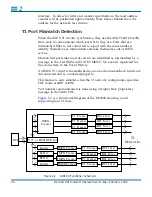
All incoming conÞgured T1 lines, with their respective clocks, are received
into a standard T1 framer. The output of the T1 framer is fed into the
IMUX framer.
Data coming into the DL3800 DS1 Inverse Multiplexer is stored in
N
independent buffers, where
N
is the number of conÞgured input channels.
From these buffers, the data will be read and IMUX framing removed.
When the incoming signal is framed on the inverse mux frame, the framer
will start loading its Dual Port RAM. The address to the Dual Port RAM is
derived from the 16-bit inverse mux frame. The software will ask all
framers to latch their Dual Port RAM addresses at the same time, and by
looking at the addresses, the software can determine which network has
experienced the greatest delay.
From the receive inverse mux framer, the incoming data will go to the
receive multiplexer. The net that is last in time will be enabled to tell the
receive multiplexer when to start unloading the Dual Port RAM to the DTE
Содержание DL3800 DS1
Страница 1: ...DL3800 DS1 Inverse Multiplexer User Guide Part 098 10380 01 Rev J February 1999...
Страница 6: ...vi DL3800 DS1 Inverse Multiplexer User Guide February 1999...
Страница 12: ...Table of Contents xii...
Страница 22: ...xxii DL3800 DS1 Inverse Multiplexer User Guide February 1999...
Страница 26: ...1 4 DL3800 DS1 Inverse Multiplexer User Guide February 1999 1...
Страница 34: ...2 8 DL3800 DS1 Inverse Multiplexer User Guide February 1999 2...
Страница 128: ...C 4 DL3800 DS1 Inverse Multiplexer User Guide February 1999 C...


