4–4
Aligning the Video Monitor
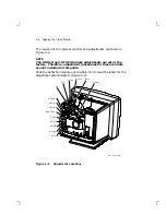
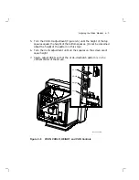
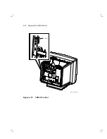
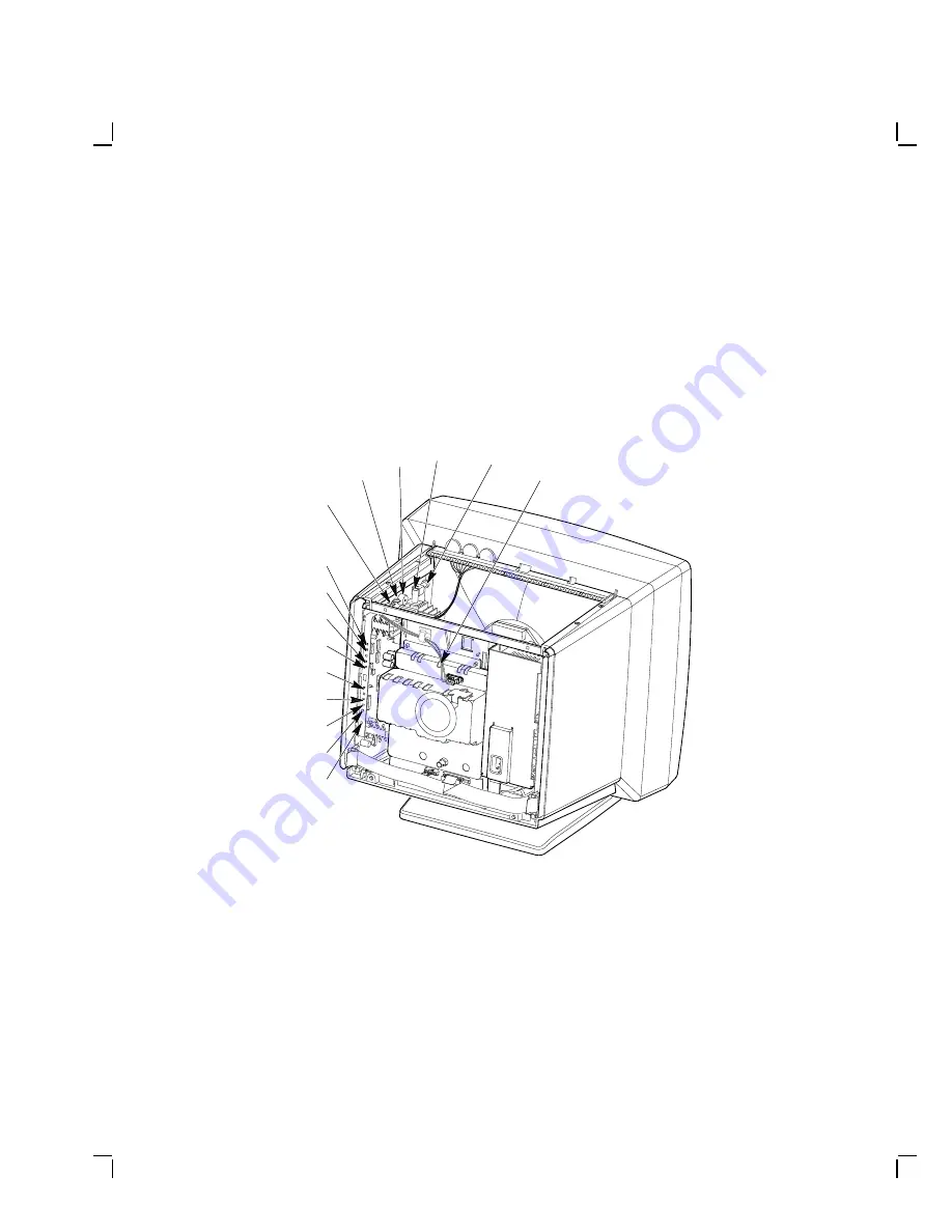
The location of the internal controls and adjustments are shown in
Figure 4–2.
NOTE
The HHOLD and DFOCUS phase adjustments are set at the
factory. Therefore, adjustment procedures for these controls
are not included in this guide.
Slide the deflection module out one-half inch to read the labels for the
adjustment potentiometers (Figure 4–2).
M A - 1 2 4 7 - 8 9 . D G
W i d t h
H C e n
G 2
G 4
V C e n
V H o l d
H H o l d
H e i g h t
V L i n
H L i n
G G a i n
H P h a s e
H P a r a b
V P a r a b
D y n P h a s e
Figure 4–2
Adjustment Locations


