background image

www.dfi.com

60

Chapter 8 Supported Software

Chapter 8

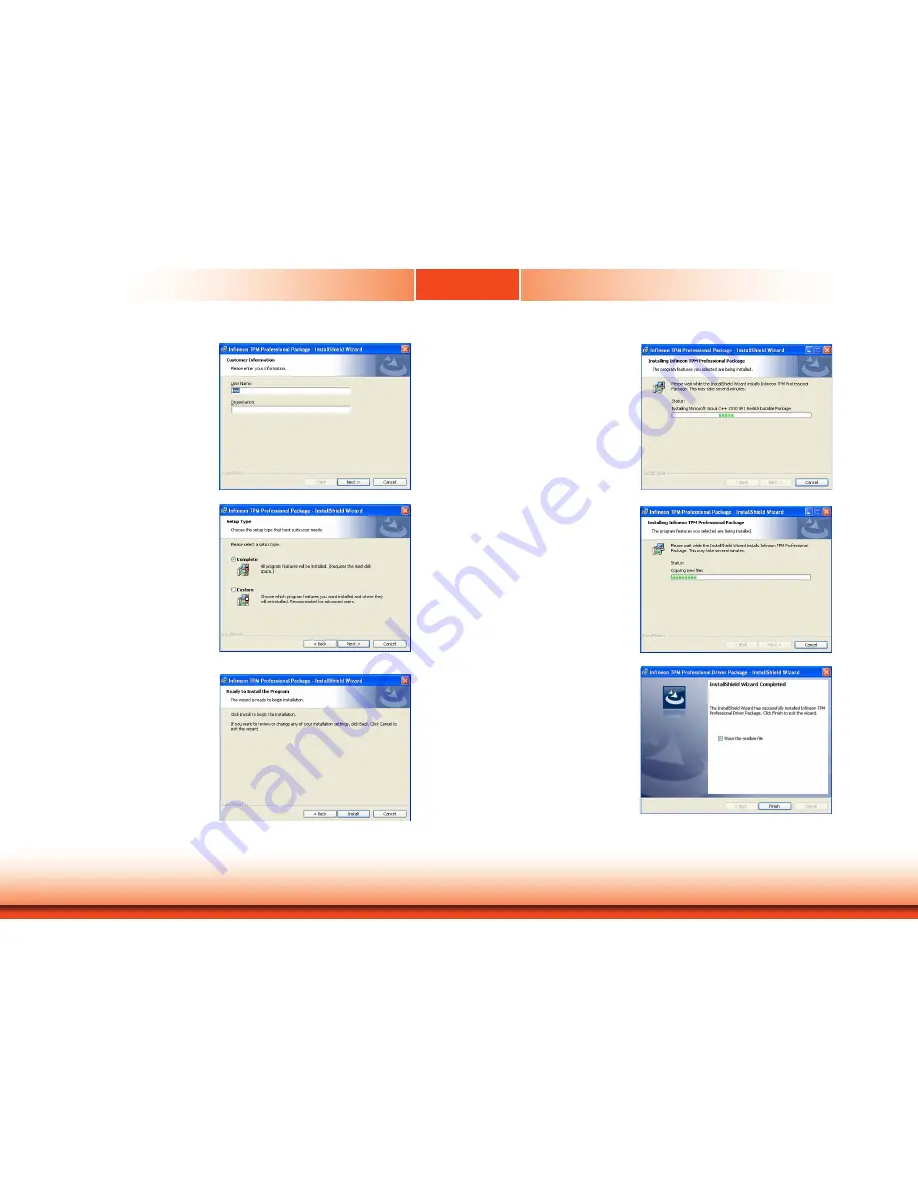
4. Enter the necessary information 

and then click “Next”.

5. Select the setup type and then 

click “Next”.

6. Click “Install” to start the 

installation.

7. TPM requires installing the Micro-

soft Visual C++ package prior to 

installing the utility. Click “Install”.

8. The setup program is currently 

installing the Microsoft Visual 

C++ package.

9. Click “Finish” to exit setup.

Содержание TPC150-SD

Страница 1: ...www dfi com 1 Chapter 1 Introduction A49700902 TPC150 SD 15 Touch Panel PC User s Manual Preliminary Version ...

Страница 2: ... owners FCC and DOC Statement on Class A This equipment has been tested and found to comply with the limits for a Class A digital device pursuant to Part 15 of the FCC rules These limits are designed to provide reason able protection against harmful interference when the equipment is operated in a residential installation This equipment generates uses and can radiate radio frequency energy and if ...

Страница 3: ...per Settings 15 Clear CMOS Data 15 Auto Power on Select 15 Backlight Power Select 16 Panel Power Select 16 LCD Inverter Power Select 17 Mini PCIe mSATA Signal Select 17 COM 1 COM 2 RS232 Power Select 18 Chapter 5 Ports and Connectors 19 Top Panel I O Ports 19 USB Ports 20 COM Serial Ports 21 Graphics Interfaces 22 I O Connectors 24 Serial ATA Connector 24 Serial ATA Power Connector 24 LVDS LCD Pan...

Страница 4: ...discharge can damage computer components without causing any signs of physical damage You must take extra care in han dling them to ensure against electrostatic build up 1 To prevent electrostatic build up leave the system board in its anti static bag until you are ready to install it 2 Wear an antistatic wrist strap 3 Do all preparation work on a static free surface 4 Hold the device only by its ...

Страница 5: ... system away from humidity Place the system on a stable surface Dropping it or letting it fall may cause damage The openings on the system are for air ventilation to protect the system from overheating DO NOT COVER THE OPENINGS Place the power cord in such a way that it will not be stepped on Do not place anything on top of the power cord Use a power cord that has been approved for use with the sy...

Страница 6: ... Key Features Model Name TPC150 SD Processor 7th Generation Intel Core Processors LAN 2 LAN ports COM 1 or 3 COM ports the additional 2 are only available upon request Display 1 x VGA 1 x DVI I DVI D signal 1 x DP USB 4 x USB 3 0 2 x USB 2 0 Audio Line out available upon request Side View Rear View ...

Страница 7: ...X 12 OpenCL 2 1 HW Decode AVC H 264 MPEG2 VC1 WMV9 JPEG MJPEG HEVC H265 VP8 VP9 HW Encode MPEG2 AVC H264 JPEG HEVC H265 VP8 VP9 Storage 2 x 2 5 SATA Drive Bay Expansion 1 x Full size Mini PCIe mSATA PCIe PCIe by default 2 x PCIe x8 Gen 3 with the riser card T100 2E or 2 x PCI 1 x Mini PCIe with the riser card X100 2P1M Audio Controller Realtek ALC888S VD2 GR Ethernet Controller 1 x Intel I210AT PC...

Страница 8: ... keyboard or mouse VGA Port Connects the VGA port of a display DP Port Connects the DisplayPort of a display DVI D Port DVI I connector Connects the DVI D port of a display LAN Ports Connect the system to a local area network Expansion Slots Provide PCIe or PCI expansion connectivity Distant Power Switch Connects to a power switch for distant power on and off control Power Switch Press to power on...

Страница 9: ...3 50 6 00 9 94 330 00 Motherboard Dimensions Chapter 1 Mechanical Dimensions TPC150 SD Bottom View Top View Right View Left View 0 6 17 11 89 37 64 73 98 104 24 126 74 145 91 163 65 170 00 0 33 02 140 78 165 10 170 00 18 02 71 51 110 38 Front View ...

Страница 10: ...he message Press DEL to run setup will appear on the screen Press the Delete key to enter the AMI BIOS setup utility Installing the Operating System Depending on the method you choose to install your system you may use a USB flash drive or install a CD ROM drive to run the Operating System CD Make sure that a SATA drive or a Mini PCIe card is already installed 1 Refer to the following chapters for...

Страница 11: ...n powered off 2 Disconnect all power cords and cables 3 The 6 mounting screws on the bottom of the system are used to secure the cover to the chassis Remove these screws and put them in a safe place for later use SODIMM socket Mini PCIe socket 4 Lift the cover up to open the system 5 The Mini PCIe and the SODIMM sockets are readily accessible after removing the chassis cover Mounting screw ...

Страница 12: ...ing procedure to install SATA drives into the system Mounting screws HDD bracket SATA drive Mounting screw SATA drive bay HDD bracket Bracket screw 3 Place the SATA drive with the HDD bracket back into the system Align the mounting holes on the HDD bracket with the mounting holes on the SATA drive bay and then use the provided mounting screws to secure the drive in place 4 Connect one end to the S...

Страница 13: ...ules For jumper settings on switching the signal betwen SATA and PCIe refer to Chapter 4 Installing a PCIe Expansion Card Slot plate bracket and screws Note The system provides two optioanl riser cards to accommodate different types of PCIe expansion slots The riser card DFI model T100 2E provides 2 x PCIe Gen3 x8 expansion slots whereas the riser card DFI model X100 2P1M provides two PCI and one ...

Страница 14: ...www dfi com 14 Chapter 3 Installing Devices Chapter 3 Front View 3 Install the bracket to secure the PCIe card in place ...

Страница 15: ... 2 10 9 1 2 10 9 1 2 COM 2 COM 3 COM 4 2 1 6 5 1 2 5 6 2 1 6 5 1 LCD Inverter Power 1 1 Mini PCIe Signal Select LCD Inverter Power Select COM1 RS232 Power Select Panel Power Select COM2 RS232 Power Select JP7 JP6 JP8 JP1 JP2 SPI Flash BIOS JP1 JP2 JP7 JP8 JP6 Digital I O Digital I O Power 1 2 1112 Front Panel 1 Auto Power on Select JP5 1 System Fan 1 1 Clear CMOS Data JP4 1 Backlight Power Select ...

Страница 16: ... 1 2 Battery 12V Power 1 2 4 3 Realtek ALC888S VD2 GR Intel I211AT 1 Chassis Intrusion SATA 3 0 1 8 4 3 Socket LGA1151 DDR4_2 SODIMM DDR4_1 SODIMM 39 40 2 1 LVDS LCD Panel 9 1 2 10 9 1 2 10 USB 2 0 USB 7 8 USB 11 12 10 9 1 2 10 9 1 2 10 9 1 2 COM 2 COM 3 COM 4 2 1 6 5 1 2 5 6 2 1 6 5 1 LCD Inverter Power 1 1 Mini PCIe Signal Select LCD Inverter Power Select COM1 RS232 Power Select Panel Power Sele...

Страница 17: ...SB 1 2 DVI D DVI I connector DP LAN 2 USB 3 4 COM1 VGA USB 3 0 USB 3 0 PS 2 USB 5 6 USB 2 0 PCIe 1 PCIe x16 Buzzer Intel Q170 1 SATA 0 1 SATA 2 Mini PCIe LPC 1 13 2 14 13 1 12 24 ATX power 1 1 2 Battery 12V Power 1 2 4 3 Realtek ALC888S VD2 GR Intel I211AT 1 Chassis Intrusion SATA 3 0 1 8 4 3 Socket LGA1151 DDR4_2 SODIMM DDR4_1 SODIMM 39 40 2 1 LVDS LCD Panel 9 1 2 10 9 1 2 10 USB 2 0 USB 7 8 USB ...

Страница 18: ... RS232 Power Select Panel Power Select COM2 RS232 Power Select JP7 JP6 JP8 JP1 JP2 SPI Flash BIOS JP1 JP2 JP7 JP8 JP6 Digital I O Digital I O Power 1 2 1112 Front Panel 1 Auto Power on Select JP5 1 System Fan 1 1 Clear CMOS Data JP4 1 Backlight Power Select JP3 1 System Fan 2 S PDIF 1 1 2 5 6 SMBus 1 CPU Fan ASMedia ASM1442 Standby Power LED 8 3 4 2 5 3 3 3 JP6 for COM 1 and JP8 for COM 2 are desi...

Страница 19: ...1 LVDS LCD Panel 9 1 2 10 9 1 2 10 USB 2 0 USB 7 8 USB 11 12 10 9 1 2 10 9 1 2 10 9 1 2 COM 2 COM 3 COM 4 2 1 6 5 1 2 5 6 2 1 6 5 1 LCD Inverter Power 1 1 Mini PCIe Signal Select LCD Inverter Power Select COM1 RS232 Power Select Panel Power Select COM2 RS232 Power Select JP7 JP6 JP8 JP1 JP2 SPI Flash BIOS JP1 JP2 JP7 JP8 JP6 Digital I O Digital I O Power 1 2 1112 Front Panel 1 Auto Power on Select...

Страница 20: ...a exchange between your computer and a wide range of simultane ously accessible external Plug and Play peripherals The system board is equipped with four onboard USB 3 0 ports USB 1 2 3 4 and two on board USB 2 0 ports USB 5 6 The 9 pin connector allows you to connect 2 additional USB 2 0 1 1 ports USB 7 8 and USB 11 12 The additional USB ports may be mounted on a card edge bracket Install the car...

Страница 21: ...2 COM 2 can be selected among RS232 RS422 and RS485 via the BIOS setup utility The pin functions of COM 1 and COM 2 will vary according to JP6 s and JP8 s setting respec tively JP6 and JP8 allow you to configure COM 1 and COM 2 to RS232 or RS232 with power Refer to COM1 COM2 RS232 Power Select in Chapter 4 for more information The serial ports are asynchronous communication ports with 16C550A comp...

Страница 22: ...ower Select Panel Power Select COM2 RS232 Power Select JP7 JP6 JP8 JP1 JP2 SPI Flash BIOS JP1 JP2 JP7 JP8 JP6 Digital I O Digital I O Power 1 2 1112 Front Panel 1 Auto Power on Select JP5 1 System Fan 1 1 Clear CMOS Data JP4 1 Backlight Power Select JP3 1 System Fan 2 S PDIF 1 1 2 5 6 SMBus 1 CPU Fan ASMedia ASM1442 Standby Power LED 8 3 4 2 5 3 3 3 RJ45 LAN Ports The two LAN ports allow the syste...

Страница 23: ...4 COM1 VGA USB 3 0 USB 3 0 PS 2 USB 5 6 USB 2 0 PCIe 1 PCIe x16 Buzzer Intel Q170 1 SATA 0 1 SATA 2 Mini PCIe LPC 1 13 2 14 13 1 12 24 ATX power 1 1 2 Battery 12V Power 1 2 4 3 Realtek ALC888S VD2 GR Intel I211AT 1 Chassis Intrusion SATA 3 0 1 8 4 3 Socket LGA1151 DDR4_2 SODIMM DDR4_1 SODIMM 39 40 2 1 LVDS LCD Panel 9 1 2 10 9 1 2 10 USB 2 0 USB 7 8 USB 11 12 10 9 1 2 10 9 1 2 10 9 1 2 COM 2 COM 3...

Страница 24: ...onnector and the other end to your Serial ATA device BIOS Setting Configure the Serial ATA drives in the Advanced menu SATA Configuration submenu of the BIOS Refer to Chapter 7 for more information Features SATA 3 0 6Gb s SATA 2 SATA 0 SATA 3 7 RXN GND TXP TXN GND 1 RXP GND The 8 bit Digital I O connector provides powering on function to external devices that are con nected to these connectors Dig...

Страница 25: ... Power 40 Panel Power LCD Inverter Power Connector Pins Function 1 GND 2 GND 3 Panel Inverter Brightness Voltage Control 4 Panel Power 5 3 3V 6 Panel Backlight On Off Control 7 12V 5V 8 12V 5 LVDS LCD Panel Connector 1 SATA 3 LAN 1 USB 1 2 DVI D DVI I connector DP LAN 2 USB 3 4 COM1 VGA USB 3 0 USB 3 0 PS 2 USB 5 6 USB 2 0 PCIe 1 PCIe x16 Buzzer Intel Q170 1 SATA 0 1 SATA 2 Mini PCIe LPC 1 13 2 14...

Страница 26: ...fer SMBus Connector SMBus 1 2 5 6 GND SMBUS_Data SMBUS_CLK 3V3DU SMBUS_Alert S PDIF Connector The S PDIF connector is used to connect an external S PDIF port Your S PDIF port may be mounted on a card edge bracket Install the card edge bracket to an available slot at the rear of the system chassis then connect the audio cable to the S PDIF connector Make sure pin 1 of the audio cable is aligned wit...

Страница 27: ...ion System Fan Chassis Intrusion Connector The board supports the chassis intrusion detection function Connect the chassis intrusion sensor cable from the chassis to this connector When the system s power is on and a chassis intrusion event occurs an alarm will sound When the system s power is off and a chassis in trusion event occurs the alarm will sound only when the system restarts 1 SATA 3 LAN...

Страница 28: ...phics card conformed to the PCI Express specifications into the PCI Express x16 slot You can choose to install T100 2E or X100 2P1M to have a different combi nation of expansion slots on the rear panel The riser card T100 2E provides two PCIe Gen3 x8 expansion slots whereas the riser card X100 2P1M provides two PCI and one Mini PCIe slots Mini PCI Express Slot The Mini PCIe socket is used to insta...

Страница 29: ...lowing 2 wall mount brackets Bracket screws 1 Select a place on the wall where you will mount the Panel PC 2 Use the provided mounting screws to attach Wall mount bracket 1 to the wall Wall mount bracket 1 Mounting screw Screw 4 Slide the Panel PC to Wall mount bracket 1 to attach the two brackets with the hooks Then tighten the screw to secure the assembly in place 3 Attach the other bracket Wall...

Страница 30: ...re you will mount the Panel PC 2 Cut out a shape on the panel that corresponds to the Panel PC s rear dimensions 383 2 mm x 310 2 mm plus 2 to allow for tolerances and ensure that the Panel PC can be fitted into the panel properly 3 Insert the Panel PC from the outside surface of the panel into the mounting hole until it is properly fitted against the panel 4 Position the mounting clamps along the...

Страница 31: ...Tighten the clamp s screw using an electric screwdriver by pressing the white plastic cap onto the back of the panel The illustration below shows that all clamps are properly mounted Slit for mounting the clamp Mounting clamp White plastic cap Note The maximum thickness of the panel s opening or wall should be 10 mm for the clamps to support the panel mount firmly ...

Страница 32: ...tup screen The BIOS Setup Utility does not require an operating system to run After you power up the system the BIOS message appears on the screen and the memory count begins After the memory test the message Press DEL to run setup will appear on the screen If the message disappears before you respond restart the system or press the Reset button You may also restart the system by pressing the Ctrl...

Страница 33: ... seconds from 00 to 59 System Date The date format is month date year Month displays the month from January to December Date displays the date from 1 to 31 Year displays the year from 1980 to 2099 Insyde BIOS Setup Utility Advanced The Advanced menu allows you to configure your system for basic operation Some entries are defaults required by the system board while others if enabled will improve th...

Страница 34: ... it s not 100 utilized Hyper Threading Enable Intel Hyper Threading Technology HT on the processor to improve performance of operating systems and software that are optimized for hyper threading technology Please check the software specifications to determine if enabling HT can be advantageous to the overall system performance Note this function is not available with the Intel Core i5 6500 Pentium...

Страница 35: ... PEG lanes directly routed from the CPU PCIe graphics devices IGFX internal graphics PCIe PCIe graphics devices PEG PCIe Graphics devices connected to PEG lanes directly routed from the CPU IGFX internal graphics Internal Graphics Device Enable disable or automatically detect the internal graphics Boot display Prioritize device combination for display during system boot with the following options ...

Страница 36: ...etection of the high definition audio devices Disabled High definition audio devices will be unconditionally disabled Enabled High definition audio devices will be unconditionally enabled Auto High definition audio devices will be enabled if present and disabled otherwise SATA Configuration This section configures SATA controllers ...

Страница 37: ...ng Intel Rapid Storage Technology on the Serial ATA devices For more information please see Chapter 9 RAID Serial ATA Port 0 to 3 and Hot Plug Enable or disable each Serial ATA port and its hot plug function USB Configuration This section configures the parameters of the USB devices Legacy USB Support Disabled Disable USB keyboard mouse storage support Enabled Enable USB keyboard mouse storage sup...

Страница 38: ...rt PCIE 1 PCIE1 expansion slot Intel I210 Gigabit Ethernet port Intel I219 Gigabit Ethernet port Full size Mini PCIe Intel I210AT Intel I219LM For each PCIe root port above configure the following parameters Enable Disable Enable or disable this PCI Express root port PCIe Speed Select the speed of the PCI Express root port Auto Gen1 2 5 GT s Gen2 5 GT s or Gen3 8 GT s Hot Plug Enable or disable th...

Страница 39: ...hen updating the BIOS Active Management Technology Support The section allows you to enable or disable the Intel Active Management Technology Intel AMT BIOS extension Refer to Chapter 9 Intel AMT Settings for more information Intel AMT Support Enable or disable Intel Active Management Technology BIOS extension Un Configure ME Clears all ME related configurations without requiring a password on the...

Страница 40: ...he BIOS setup utility Network Device List The Device Manager screen is displayed And if the Network Stack or the PXE Boot to LAN option is enabled from the Boot menu the Network Device List should be shown in the Device list Select Network Device List to view all of the detected network devices For each network device you can select to view and configure its settings In addition you can select eit...

Страница 41: ... between 0 and 255 Local Gateway Enter the gateway address in the IPv4 format Local DNS Domain Name System Servers Enter DNS Domain Name System server IP addresses in the IPv4 format IPv6 Network Configuration If you select to use IPv6 network settings enter the Interface ID 64 bit Policy Select either automatic or manual And select Advanced Configuration to configure IPv6 network address manually...

Страница 42: ...uld be turned on and operate at the designated speed The range of the temperature is from 0 to 127o C Fan Speed Count 1 to Fan Speed Count 4 Set the fan speed The range is from 1 lowest speed 100 full speed COM Port 1 and COM Port 4 Enable or disable each serial port Disable Disable this serial port Enable Enable this serial port It also shows the Base I O address and the assigned interrupt number...

Страница 43: ...Chapter 7 BIOS Setup 43 www dfi com Chapter 7 PC Health Status This section displays PC health information such as the voltages and CPU and system temperatures ...

Страница 44: ...T_100 VT_UTF8 or PC_ANSI Baud rate 115200 57600 38400 19200 9600 4800 2400 or 1200 Data bits 8 bits or 7 bits Parity None Even or Odd Stop bits 1 bit or 2 bits Flow control None RTS CTS or XON XOFF This is the global setting for all of the designated serial ports for the console redirection function COMA to COMD PCI Serial Port Enable or disable the serial redirection function for each of the seri...

Страница 45: ...etwork Stack This option is shown only when the boot type is set to Dual or UEFI Enable or disable UEFI network stack It supports the operation of these functions or software Windows 8 BitLocker Network Unlock UEFI IPv4 IPv6 PXE and legacy PXE op tion ROM If this function is enabled you can then go to Advanced UEFI Device Manager to configure network settings for network connection under the UEFI ...

Страница 46: ...h depending on the Boot Type selected Exit This section configures the parameters for exiting the BIOS setup utility Exit Saving Changes Select this field and press Enter to exit BIOS setup and save your changes Load Optimal Defaults Select this field and press Enter to load the optimal defaults Discard Changes Select this field and press Enter to exit the BIOS setup without saving your changes Sa...

Страница 47: ...ot be used to replace one which has been utilized on other system boards 3 If you do not follow the methods above the Intel Management Engine will not be updated and will cease to be effective Updating the BIOS To update the BIOS you will need the new BIOS file and a flash utility Please contact techni cal support or your sales representative for the latest BIOS file and the firmware update utilit...

Страница 48: ...vice Software Intel Graphics Driver Intel Rapid Storage Technology Intel LAN Driver Kernel Mode Driver Framework For Windows 7 only Intel ME Driver Intel USB 3 0 Driver For Windows 7 only Audio Driver Intel Serial IO Driver PenMount Windows Universal Driver TPC Series Hotkey Driver Trusted Platform Driver optional Microsoft Framework 4 5 2 Intel Chipset Device Software The Intel Chipset Device Sof...

Страница 49: ...nstall the graphics driver Click Next to continue By default the Automatically run WinSAT and enable the Windows Aero desktop theme is enabled With this enabled after the graphics driver is installed and the system is rebooted the screen will turn blank for 1 to 2 minutes while WinSAT is running before the Windows 7 Windows 8 1 Windows 10 desktop appears The blank screen period is the time Windows...

Страница 50: ... Yes I want to restart this computer now and then click Finish Restarting the system will allow the new software installation to take effect Audio Drivers Please use the following procedure to install audio drivers 2 Click Yes I want to restart my computer now and then click Finish Restarting the system will allow the new software installation to take effect 1 Setup is ready to install the driver ...

Страница 51: ...all the PenMount Windows Universal Driver 1 Setup is ready to install the driver Click Next 2 Click on I agree 3 Click on Browse to install the driver in a different folder and select another folder Click on Install to begin the installation 4 Setup is currently installing the utility 5 After completing installa tion click Finish ...

Страница 52: ...nstall the driver Click Next to continue 2 Read and License Agree ment and click I accept the terms in the license agreement if you agree the terms in the agree ment and then click Next 3 Select the program features you want to install and then click Next 4 Click Install to begin the installation 5 After the installation is complete click Finish to exit setup ...

Страница 53: ...l Mode Driver For Windows 7 only Please use the following procedure to install the Kernel Mode Driver Framework 1 Click Yes to install the update 2 The update is being in stalled now 3 Click Restart Now to restart your computer when the installation is complete ...

Страница 54: ...all the driver Click Next to continue 2 Read and License Agree ment and click I accept the terms in the license agreement if you agree with the terms in the agreement and then click Next 3 Setup is currently installing the driver After the instal lation is complete click Next 4 Please wait while the prod uct is being installed 5 After the installation is complete click Finish to exit setup ...

Страница 55: ...lling the driver After the installation is complete click Next 5 After the installation is complete click Finish USB 3 0 Driver For Windows 7 Please use the following procedure to install the USB 3 0 Drivers 2 Read the license agreement and then click Yes if you agree with the terms in the agreement 1 Setup is ready to install the driver Click Next to continue ...

Страница 56: ...mation and then click Next IO Driver For Windows 7 64 bit and 10 Please use the following procedure to install the Intel Serial IO Driver 1 Setup is ready to install the driver Click Next to continue 2 Read the license agreement care fully Click I accept the terms in the License Agreement if you agree with the terms in the agreement and then click Next ...

Страница 57: ...now extracting files Note Before installing Microsoft Framework 4 5 2 make sure you have updated your Windows 7 operating system to Service Pack 3 2 Read the license agreement care fully Click I have read and accept the terms of the License Agree ment if you agree with the terms in the agreement and then click Next 5 Setup is now installing the driver 6 Click Finish to exit setup ...

Страница 58: ...formance and power management for the stor age subsystem Please use the following procedure to install the Intel Rapid Storage Driver 4 Click Finish to exit setup 3 Setup is now installing the driver 1 The setup program is preparing to install the driver Please exit all programs before continuing with the installation 2 Read the license agreement carefully accept the terms of the License Agreement...

Страница 59: ...our system 5 Click Yes I want to restart this computer now then click Finish Restarting the system will allow the new software installation to take effect 1 The setup program is preparing to install the driver 2 The setup program is now ready to install the utility Click Next to continue 3 Click I accept the terms in the license agreement if agree with the terms in the agreement and then click Nex...

Страница 60: ...ck Next 5 Select the setup type and then click Next 6 Click Install to start the installation 7 TPM requires installing the Micro soft Visual C package prior to installing the utility Click Install 8 The setup program is currently installing the Microsoft Visual C package 9 Click Finish to exit setup ...

Страница 61: ...art your system TPC Series Hotkey Driver Please use the following procedure to install the TPC Series Hotkey Driver 1 The InstallShield Wizard Setup is preparing to install please wait 2 Setup is ready to install the driver Click Next 3 Click Install to begin the installation ...

Страница 62: ...s below to complete the setting 1 After the TPC Series Hotkey Driver is installed successfully the system will execute the util ity automatically when you power on the computer You can find the four hotkeys on the bottom right side of the screen 2 Click the utility twice to bring up the backlight brightness setting 3 Enter the value for the backlight brightness for both day and night modes The def...

Страница 63: ...n existing drive and a new drive but the size of the new drive must be the same or larger than the existing drive Settings To enable the RAID function the following settings are required 1 Connect the Serial ATA drives 2 Enable RAID in the BIOS 3 Create a RAID volume 4 Install the Intel Rapid Storage Technology Utility Step 1 Connect the Serial ATA Drives Refer to Chapter 3 for details on connecti...

Страница 64: ...ume space to leave space for the second volume 9 Press Enter to create the volume 10 At the prompt press Y to confirm volume creation 11 Select 4 Exit and press Enter 12 Press Y to confirm exit Note These steps are cited from the Intel Support site Set Up a System with Intel Matrix RAID Technology Article ID 000005789 Step 3 1 Create a RAID Volume if the boot type is UEFI If the boot type is set t...

Страница 65: ... 1 Insert the provided DVD into an optical drive 2 Click Intel Rapid Storage Technology Utility on the main menu 4 Read the license agree ment and click I accept the terms in the License Agreement Then click Next 3 Setup is ready to install the utility Click Next 5 The screen displays all available drives Select Create RAID volume to create a RAID volume 6 Use the up or down arrow keys to select t...

Страница 66: ...irements and installa tion information then click Next 7 Confirm the installation and click Next 6 Click Next to install to the default folder or click change to choose another destination folder 8 Click Yes I want to restart this computer now to complete the installation and then click Finish ...

Отзывы: