ENGLISH
11
thermal breaker located inside the winding - this stops the
compressor when motor temperature reaches excessively
high values (180
o
C). If the breaker is tripped, the compressors
restart automatically after 10 to 15 minutes.
ADJUSTING OPERATING PRESSURE
You do not have to use the maximum operating pressure
at all times. On the contrary, the pneumatic tool being used
often requires less pressure. On compressors supplied with
a pressure reducer, operating pressure must be correctly
adjusted.
Adjust pressure to the required value by turning the knob (4)
clockwise to increase pressure and anti-clockwise to reduce
it. When you have obtained optimum pressure, lock the knob
by pressing it downward. For pressure reducers equipped
without a pressure gauge, the set pressure can be seen on
the graduated scale located on the reducer body.
On pressure reducers equipped with a pressure gauge,
pressure can be seen on the gauge itself.
WARNING:
Some pressure regulators do not have “push to
lock”, therefore simply turn the knob to adjust the pressure.
STOPPING THE COMPRESSOR
1. Turn or press the switch/button into position “0” (according
to the type of pressure switch fitted on the compressor).
DO NOT turn off the unit by switching off at the socket or
pulling out the plug.
2. Turn regulator knob (4) counterclockwise until fully closed.
Ensure regulated pressure gauge reads 0 bar (0 psi).
3. Remove hose and accessory.
4. Drain the air tank, see
Draining Air Tank
under Maintenance.
Ensure air tank pressure gauge reads 0 bar (0 psi).
Maintenance
m
WARNING: To reduce the risk of injury, turn unit off and
disconnect machine from power source before installing and
removing accessories, before adjusting or changing setups or
when making repairs.
An accidental start-up can cause injury.
The following procedures must be followed when
maintenance or service is performed on the air compressor.
NOTE
: Allow air compressor to cool down before starting
service.
NOTE
: All compressed air systems contain maintenance parts
(e.g., oil, filters, separators) that are periodically replaced.
These used parts may contain substances that are regulated
and must be disposed of in accordance with local, state, and
federal laws and regulations.
NOTE
: Take note of the positions and locations of parts during
disassembly to make reassembly easier.
NOTE
: Any service operations not included in this section
should be performed by a
D
e
WALT
factory service center or a
D
e
WALT
authorized service center.
DRAINING AIR TANK
The condensation in the tank must be drained daily by
opening the drain tap (2) under the tank. Take care if there is
compressed air inside the cylinder, as water could flow out
with considerable force.
1. Verify that the compressor is turned “Off”.
2. Holding the handle, tilt the compressor toward the drain
valve so it is positioned at the bottom of the tank.
3. Turn the drain valve to open.
4. Keep the compressor tilted until all moisture has been
removed.
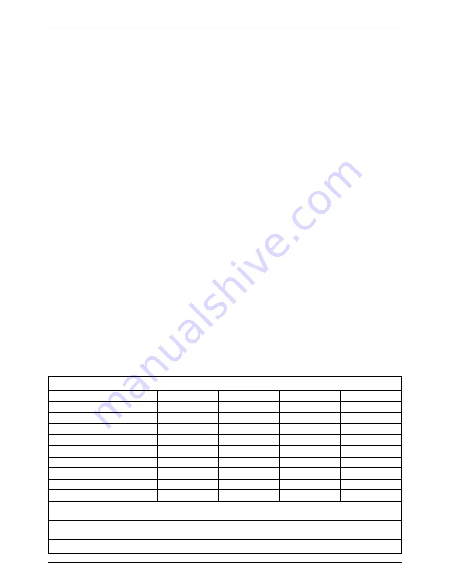
MAINTENANCE CHART
Procedure
Daily
Weekly
Monthly
1 year or 200 Hours
Check safety valve
X
Inspect air filter
+
X
Drain air tank
X
Check pump oil level
X
Change pump oil (DPC16PS Only)**
+
X
Oil leak inspection
(DPC16PS Only)
X
Check for unusual noise/vibration
X
Check for air leaks*
X
Clean compressor exterior
X
* To check for air leaks apply a solution of soapy water around joints. While compressor is pumping to pressure and after pressure
cuts out, look for air bubbles to form.
** The pump oil must be changed after the first 20 hours of operation. Thereafter, when using
D
e
WALT
synthetic or SAE 40, non-
detergent air compressor oil, change oil every 200 hours of operation or once a year, whichever comes first.
+
Perform more frequent in dusty or humid conditions
Содержание DPC10RC-GB
Страница 1: ...DPC6MRC QS DPC6MRC GB DPC10RC QS DPC10RC GB DPC10RC LX DPC16PS QS DPC16PS GB DPC16PS LX ...
Страница 196: ......
Страница 197: ......
Страница 198: ......


