


User Manual DEV 7xxx Optribution® Modules
8
Copyright DEV Systemtechnik GmbH 2012-2017
In addition, the DEV 7232 has a built-in limiter to prevent clipping of the laser diode
if the RF input level becomes too high. The DEV 7233 and the DEV 7251 additionally
provide manual gain control and the automatic OMI optimization feature, which
are to be configured via the Web Interface of the Optribution® chassis.
Finally, an RF monitoring port (
6
, labelled "
Mon
") is available at the transmitter
modules DEV 7232, DEV 7233, DEV 7238, and DEV 7251.
Note:
For selected optical transmitter modules applied in an Optribution® chassis
providing a Web Interface and/or SNMP: All LEDs of the module may blink
shortly as a receipt after the boot phase and after an operation mode change.
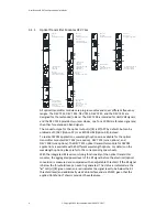
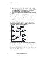
3.1.2
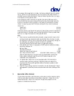
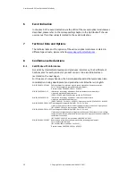
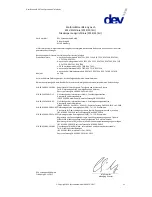
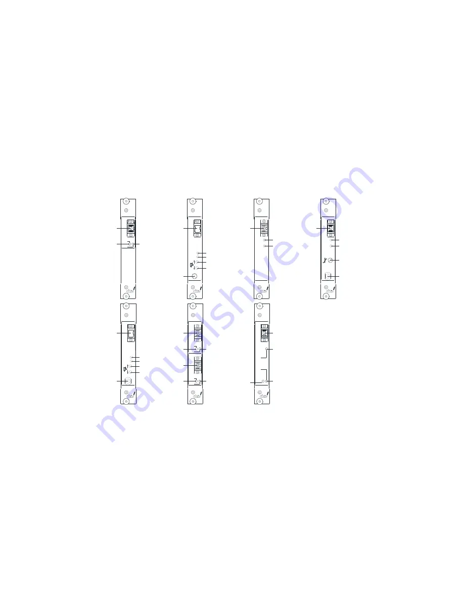
Optical Receiver Modules DEV 73xx
1 O p tic a l In p u t
2 O p tic a l M o n ito r L E D
3 R F L E D
4 G a in U p B u tto n
5 G a in D o w n B u tto n
6 M o n ito r P o rt
D E V 7 3 3 2
A d v a n c e d
O p trib u tio n R e c e iv e r
D E V 7 3 3 3
T o p P e rfo rm a n c e
O p trib u tio n R e c e iv e r
D E V 7 3 3 1
B a s ic
O p trib u tio n R e c e iv e r
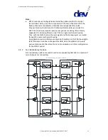
1 O p tic a l In p u t
2 O p tic a l M o n ito r L E D
3 R F L E D
D E V 7 3 3 7
B a s ic U H F /V H F
O p trib u tio n R e c e iv e r
1 O p tic a l In p u t
2 O p tic a l M o n ito r L E D
3 R F L E D
6 M o n ito r P o rt
7 S lo p e P o te n tio m e te r
L -B a n d R x
R F
O p t.
In
O p t.
R F
M o n
L -B a n d R x
In
O p t.
R F
1 0 M H z R x
In
M o n
O p t.
R F
C A T V -B a n d R x
In
3
2
1
1
6
2
3
4
5
2
3
7
6
2
3
D E V 7 3 3 5
R e fe re n c e
O p trib u tio n R e c e iv e r
1 O p tic a l In p u t
2 O p tic a l M o n ito r L E D
3 R F L E D
1
1
1 A /1 B O p tic a l In p u t A /B
2 A /2 B O p tic a l M o n ito r L E D A /B
3 A /3 B R F L E D A /B
D E V 7 3 4 1
B a s ic T w in
O p trib u tio n R e c e iv e r
O p t.
In B
L -B a n d R x
R F
O p t.
In A
R F
M o n
R F
O p t.
C A T V -B a n d R x
In
1 A
2 A
1 B
2 B
3 A
3 A
2
3
4
5
1 O p tic a l In p u t
2 O p tic a l M o n ito r L E D
3 R F L E D
4 G a in U p B u tto n
5 G a in D o w n B u tto n
6 M o n ito r P o rt
D E V 7 3 3 8
A d v a n c e d U H F /V H F
O p trib u tio n R e c e iv e r
1
6
D E V 7 3 4 4
O p trib u tio n R e c e iv e r
1 0 M H z , 7 0 0 ...2 3 0 0 M H z
1 O p tic a l In p u t
2 O p tic a l M o n ito r L E D
3 a R F L E D L -B a n d
3 b R F L E D 1 0 M H z
O p t.
R F
R F
L -B a n d
1 0 M H z
R x
In
2
1
3 a
3 b
All optical receiver modules are plug-in modules and cover different frequency
ranges. The DEV 7331, DEV 7332, DEV 7333, and the DEV 7341 are designed for the
(extended) L-Band. The DEV 7335 is intended for the reception of 10 MHz reference
signals. The DEV 7337 and the DEV 7338 are designed for UHF/VHF signals; and the
DEV 7344 provides two detector diodes, one for a 10 MHz reference signal and the
other for extended L-Band signals.
The connector type for the optical input(s) (
1
) is SC/APC by default, but can be
ordered as FC/APC (Option 07) or as E2000 HRL (Option 08), instead.
The light condition detection serves as the light status indication and may signalize
that no or not enough optical power is received by the detector diode. An event in
this area is indicated via the "
Opt.
" LED (
2
) turning from green to red; additionally
the status of the light condition detection is indicated via Web Interface and via
SNMP, given that the Optribution® chassis provides these features. Possible
reasons for this event are: