


User Manual DEV 7xxx Optribution® Modules
18
Copyright DEV Systemtechnik GmbH 2012-2017
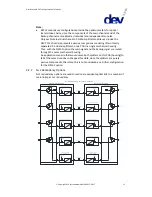
Note that in a regular redundancy case -the signal transmission of a main channel is
realized via the redundancy channel- there is no automatic return to normal
operation. The switching back to normal operation (on both sides) has to be
performed in Local Mode via Web Interface or in Remote Mode via SNMP.
Note:
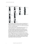
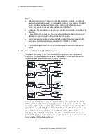
Depending on the type of Optribution® chassis, one or more n+1 redundancy
options can be installed. Also the size of the redundancy unit(s) (4+1…16+1)
which can be applied depends on the type of chassis.
In addition to the installation of n+1 redundancy option(s) within an
Optribution® chassis it is usually possible to install a number of additional
optical modules without applied redundancy. This number of additional optical
modules depends on the available space within the chassis.
If available for the chassis, an n+1 redundancy option on the receiver side can
be combined with distribution options or with IRD controlled switch options.
N+1 redundancy options are not available for 1 RU Optribution® chassis and for
chassis that do not provide a CPU (module).
N+1 redundancy options are not available for optical modules equipped with
two diodes for different frequency ranges (DEV 7244 & DEV 7344).
It is not possible to combine n+1 redundancy options with 1+1 redundancy
options.
4
Installation Instructions
4.1
Scope of Delivery
Please refer to the corresponding Optribution® chassis user manual for the scope of
delivery.
4.2
Installation of the Product
For the installation of the Optribution® chassis and for the installation and the
exchange of optical modules, please refer to the corresponding Optribution®
chassis user manual.
4.3
Device Factory Settings
The factory settings for the specifics of the applied Optribution® chassis are subject
of the corresponding Optribution® chassis user manual. Here, the factory settings
for the optical modules are described.
4.3.1
Factory Settings for the Optical Modules
All optical transmitter modules or optical receiver modules provide RF level
monitoring functionality, i.e. the aggregated power level of the RF signal is
measured and compared with an RF threshold level. If the signal level is below the
threshold level, an event is generated. This, for instance, enables an Optribution®
chassis with applied redundancy switching functionality to control the switching
autonomously. The factory setting for the RF threshold level is:
RF threshold level:
(20 dB above lower limit)