


User Manual DEV 7xxx Optribution® Modules
Copyright DEV Systemtechnik GmbH 2012-2017
3
1
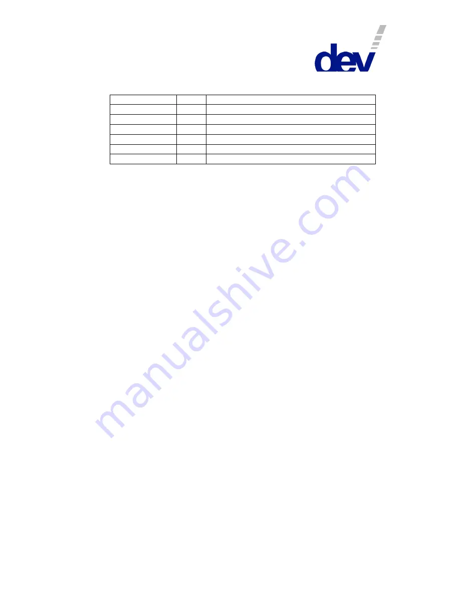
Revision History
Revision (Date)
Author
Short Description
A (18-Apr-2012)
WP
Initial version
(…)
I (02-Feb-2017)
WP
Added NSPoF description
J (22-Mar-2017)
WP
Supplementations on NSPoF description
K (10-May-2017)
WP
Minor corrections and supplementations
L (02-Nov-2017)
WP
Reworked document format
2
Introduction
Thank you for purchasing DEV Systemtechnik Optribution® products.
This user manual is intended to supplement the documentation of the available
Optribution® chassis with information concerning the optical modules that are to
be applied in these chassis.
DEV Systemtechnik offers various optical modules for the conversion of RF signals.
Additionally, several optical modules are available in order to amplify, to combine,
or to distribute the optical signals. These modules can be installed in 1 RU, 3 RU,
4 RU, or in outdoor Optribution® chassis, which are capable to manage a different
number of signal channels.
There are separate user manuals for the different Optribution® chassis and this
common user manual for the Optribution® modules. Since the Optribution®
module product portfolio is continually changing, this division is supposed to
improve the documentation update process.
In addition to the description of the optical modules, this Optribution® modules
user manual explains the general redundancy principles.
DEV Systemtechnik GmbH declares that this equipment meets all relevant
standards and rules. Each unit carries a CE mark.
Please read all instructions before installation or usage of the equipment!
2.1
Warranty
Each product has a warranty against defects in material and workmanship for a
period of two years from the date of shipment.
During the warranty period DEV Systemtechnik will, at its option, either repair or
replace the product if it turns out to be defective.
For warranty, service, or repair, the product must be returned to DEV System-
technik. The customer has to pay shipping charges to DEV Systemtechnik and
DEV Systemtechnik will pay shipping charges to return the product to the customer.
However, the customer is obliged to pay all duties, all taxes, and all other additional
costs arising from the shipment of the product.
DEV Systemtechnik warrants that the software and firmware designated by
DEV Systemtechnik for use with the product will execute its programming
instructions if installed properly. DEV Systemtechnik does not warrant that the
operation of the product, software, or firmware will be uninterrupted or error-free.