


User Manual DEV 7xxx Optribution® Modules
Copyright DEV Systemtechnik GmbH 2012-2017
19
For example, if the lower limit is -50 dBm, the factory setting for the RF threshold
level is -30 dBm. The RF threshold level can be adjusted via the Web Interface or
via SNMP –given that the Optribution® chassis provides these features- in a range
that depends on the applied module.
Some optical transmitter modules are capable of providing LNB power at the
RF input. With the current monitoring functionality, the current delivered by the
RF input is monitored. If the measured current exceeds the defined monitoring
interval, an event is generated. The factory settings for the current monitoring
interval are:
Lower Limit:
100 mA
Upper Limit:
350 mA
The lower and the upper limit of the current monitoring interval can be adjusted via
the Web interface or via SNMP -given that the Optribution® chassis provides these
features- in a range that depends on the applied module.
Note:
Some modules provide additional functionality, e.g. gain and/or slope control
and may provide operational elements (a potentiometer or buttons) to make
the adjustments locally at the module; alternatively (or exclusively) changes on
the settings may be performed via Web Interface or via SNMP.
The factory settings for these parameters are application-specific.
If the Optribution® chassis is equipped with EDFA optical amplifier module(s),
the factory settings are:
(Manual) Gain:
0 dB
Operation/Gain Mode:
mute
Automatic Output Power Setpoint:
0 dBm
Input Power Limit/Threshold:
(lower limit of the interval, e.g. -3 dBm)
Note that
(Manual) Gain
is supported only by selected EDFA, and that the
factory default setting for
Input Power Limit/Threshold
depends on the
capabilities of the applied EDFA.
For Optribution® chassis that are not equipped with a CPU (module) it is
possible to alter the factory settings of optical modules according to the
requirements of the specific application before the delivery, please contact
DEV Systemtechnik.
Note that if an exchange module is inserted in a slot of an Optribution® chassis
with applied CPU (module), the new module inherits the stored settings of this
slot.
5
Operation of the Product
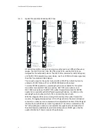
The operational elements (potentiometer, push buttons) and the indicators (LEDs)
of the several optical modules were described in chapter 3.1. Please refer to the
related Optribution® chassis user manual for the general perspective on the
operation of Optribution® products.