


User Manual DEV 7xxx Optribution® Modules
Copyright DEV Systemtechnik GmbH 2012-2017
17
this main receiver channel, i.e. the RF threshold level setting and possibly the slope
(or tilt) and/or the gain setting(s). If gain control is available, the RGC (Redundancy
path Gain Compensation) functionality becomes active in addition. Not transferred
is the setting for surveillance enable.
All in all, this is the regular redundancy case for any defective main channel within
the n+1 redundancy.
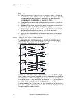
O p tic a l
E le c tric a l
E le c tric a l
O p tic a l
R e d u n d a n c y O p tic a l
T ra n s m itte r M o d u le
O p tic a l
E le c tric a l
E le c tric a l
O p tic a l
O p tic a l
E le c tric a l
E le c tric a l
O p tic a l
O p tic a l
E le c tric a l
E le c tric a l
O p tic a l
O p tic a l
E le c tric a l
E le c tric a l
O p tic a l
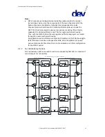
O p tic a l T ra n s m itte r M o d u le A
O u t A
O u t B
O u t C
O u t D
In A
In B
In C
In D
O p tic a l T ra n s m itte r M o d u le B
O p tic a l T ra n s m itte r M o d u le C
O p tic a l T ra n s m itte r M o d u le D
R e d u n d a n c y O p tic a l
R e c e iv e r M o d u le
O p tic a l R e c e iv e r M o d u le A
O p tic a l R e c e iv e r M o d u le B
O p tic a l R e c e iv e r M o d u le C
O p tic a l R e c e iv e r M o d u le D
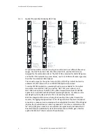
4 + 1 R e d u n d a n c y S w itc h M o d u le
4 + 1 R e d u n d a n c y S w itc h M o d u le
4 + 1 R e d u n d a n c y : R e d u n d a n c y O p e ra tio n C h a n n e l C
T ra n s m itte r C h a s s is
R e c e iv e r C h a s s is
O p tic a l F ib e r
O p tic a l F ib e r
O p tic a l F ib e r
O p tic a l F ib e r
O p tic a l F ib e r
R F L e v e l
R F L e v e l
R F L e v e l
R F L e v e l
R F L e v e l
R F L e v e l
R F L e v e l
R F L e v e l
R F L e v e l
R F L e v e l
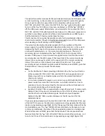
If the RF level of the redundancy channel is below the defined RF threshold level [or
if the light condition of the redundancy channel is "Fail"] after the transmitter side
has switched, it is assumed that there is no electrical RF input signal available at the
corresponding main channel on the transmitter side [or the optical transmission of
the redundancy channel is detected as being defective]. Thus, the receiver side
commands the transmitter side to switch back to normal operation and this main
channel is excluded then from further autonomous switching control. The main
channel is considered valid for autonomous switching again as soon as a valid
RF signal [and the light condition being "OK"] is detected on the receiver side
(meaning, that the optical transmission is detected as "OK" and that an RF signal is
applied at the main channel on the transmitter side again). With this logic, all
components of the transmission path between the electrical switches on the
transmitter side and on the receiver side are checked.