


User Manual DEV 7xxx Optribution® Modules
12
Copyright DEV Systemtechnik GmbH 2012-2017
3.2
Redundancy Principles
Without optical link redundancy, the RF inputs of optical transmitter modules are
made accessible in an Optribution® chassis via cabling options.
Cabling options are used for the RF outputs of optical receiver modules as well;
additionally there are offered distribution options and IRD controlled switch
options for selected Optribution® chassis.
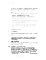
If optical link redundancy is required in an application, 1+1 or n+1 redundancy
options can be installed in some Optribution® chassis. In the following, the principle
of both types of optical redundancy is explained.
3.2.1
1+1 Redundancy Options
1+1 redundancy options are used to realize a redundant optical link (i.e. a backup
link) to a dedicated main link per 1+1 redundancy.
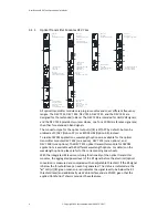
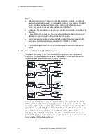
An optical 1+1 redundancy consists of the 1+1 redundancy unit in the transmitter
(Tx) chassis and of the 1+1 redundancy unit in the receiver (Rx) chassis.
On the Tx side, the RF input signal is fed to the input ports of the main and of the
backup optical transmitter channel via a 1:2 passive splitter. Thus, the optical
transmission is realized via two optical fibers. On the Rx side the RF output of the
main and of the backup optical receiver channel are forming the inputs of the 2:1
redundancy switch. The output of the redundancy switch is the output of the 1+1
redundancy.
At least the Rx chassis of 1+1 redundancy units requires a CPU (module) to enable
the switching between the main channel and the backup channel. With the CPU
(module) equipped, the Optribution® chassis provides a Web Interface, SNMP, and
the capability to switch autonomously.
D u a l 2 :1
S w itc h M o d u le
O u t A
R e c e iv e r C h a s s is
B a c k u p O p tic a l
R e c e iv e r M o d u le A
M a in O p tic a l
R e c e iv e r M o d u le A
O p tic a l
E le c tric a l
O p tic a l
E le c tric a l
In A
T ra n s m itte r C h a s s is
B a c k u p O p tic a l
T ra n s m itte r M o d u le A
M a in O p tic a l
T ra n s m itte r M o d u le A
1 + 1 R e d u n d a n c y : N o rm a l O p e ra tio n
D u a l 1 :2
S p litte r M o d u le
E le c tric a l
O p tic a l
E le c tric a l
O p tic a l
O u t B
B a c k u p O p tic a l
R e c e iv e r M o d u le B
M a in O p tic a l
R e c e iv e r M o d u le B
O p tic a l
E le c tric a l
O p tic a l
E le c tric a l
In B
B a c k u p O p tic a l
T ra n s m itte r M o d u le B
M a in O p tic a l
T ra n s m itte r M o d u le B
E le c tric a l
O p tic a l
E le c tric a l
O p tic a l
O p tic a l F ib e r
O p tic a l F ib e r
O p tic a l F ib e r
O p tic a l F ib e r
R F L e v e l
R F L e v e l
R F L e v e l
R F L e v e l
R F L e v e l
R F L e v e l
R F L e v e l
R F L e v e l
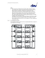
If the 1+1 redundancy is in normal operation -i.e. the Rx redundancy unit is
switched to the main channel and the backup channel is not used (as shown for two
1+1 redundancies (A and B) in the figure above)- and if Auto Mode is activated on
the Rx side, the RF level status and the light condition detection of the main and of
the backup optical receiver channels are continuously monitored.