


Customer Documentation DEV 5071
8
Copyright DEV Systemtechnik GmbH 2007-2017
3.2
MODULES DESCRIPTION
This paragraph points out the functionality of the power supply modules and
the CPU module.
3.2.1
Power Supply Module
The product can be equipped with 1…4 power supply modules to deliver the
required power. It is recommended to install an additional power supply
module for the required power in order to provide redundancy if one of the
modules fails.
Power supply modules can be removed, installed, and/or exchanged even
during the operation of the device. Upgrading the DEV 5071 via an additional
power supply is possible as well; please refer to chapter 4.2.3.
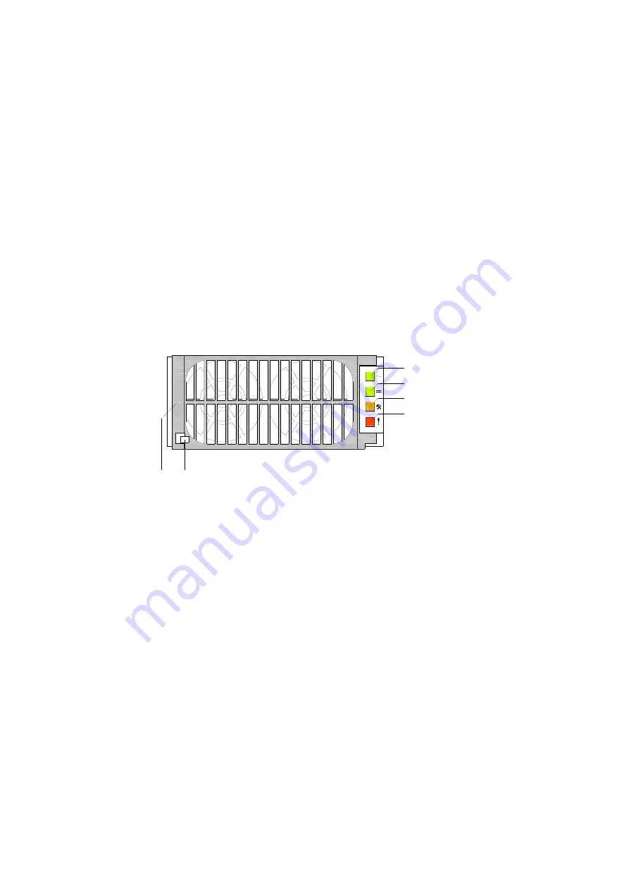
3
4
5
6
1
2
Plastic handle (1) and metal lever (2):
These elements are necessary for the mechanical handling of a power
supply module (chapter 4.2.3).
AC LED (3):
This green LED being lit indicates whether the AC connection of the
corresponding power supply module is supplied with AC. If the LED is
blinking, the input voltage is out of range.
DC LED (4):
This green LED being lit indicates that the power supply module is
delivering DC to the output terminals of the device. If the LED is blinking,
an overload situation is signalized.
Excess Temperature / Service LED (5):
This amber LED being lit indicates excess temperature of the power
supply module. If the LED is blinking it indicates a service request,
please contact DEV Systemtechnik.
Error LED (6):
This red LED indicates failures of the power supply module. Reasons can
be a blown AC fuse in the unit, a defective fan, or a thermal shutdown.
Note:
If one of the power supply modules is turned off via software control, the
DC LED of this power supply module is off, indicating that it is not
delivering any output voltage.


