


6
10.
On the
CT Values
tab configure the
CT Type
an
d CT Amperage Rating.
Clear accumulated and
demand data.
11.
Select the
Realtime Values
tab for a table of current meter readings and verify the voltage,
current and power readings are correct.
12.
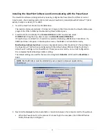
In ViewPoint, click the
Communications
tab and change communication settings, if necessary,
for the RS-485 network.
13.
Remove the RS-485 adapter from the PowerScout. Connect the PowerScout to the modbus
network.
14.
Configure the RTU/data logging equipment to receive data from the PowerScout.
•
For more information on this step, consult the instruction manual for RTU/data logger.
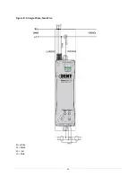
PowerScout 3 Diagram
Figure II-1: PowerScout 3 Layout – US voltage wire colors shown
Voltage Leads
I/O Port Indicator LEDs
Terminal Block for I/O
Port Connections
Modbus Address Switches
Communication LED
Terminal Block for RS-485
Connection
Terminal Block for
Current Transformer
(CT) Connections
PhaseChek
™
LEDs
Содержание PowerScout 3
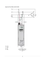
Страница 19: ...15 Figure IV 1 Single Phase Two Wire N white L1 black L2 red L3 blue ...
Страница 20: ...16 Figure IV 2 Single Phase Three Wire N white L1 black L2 red L3 blue ...
Страница 21: ...17 Figure IV 3 Three Phase Three Wire Delta N white L1 black L2 red L3 blue ...
Страница 22: ...18 Figure IV 4 Three Phase Four Wire Wye N white L1 black L2 red L3 blue ...
Страница 23: ...19 Figure IV 5 Three Phase Four Wire Delta N white L1 black L2 red L3 blue ...


