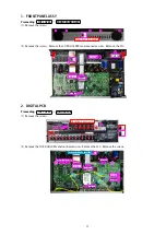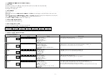
1. FRONT PANEL ASSY
Proceeding : TOP COVER
→
FRONT PANEL ASSY
(1) Remove the screws.
(2) Remove the screws. Remove the CORD HOLDERs and connector wires. Remove the FFC.
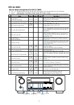
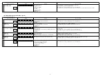
2. DIGITAL PCB
Proceeding : TOP COVER
→
DIGITAL PCB
(1) Remove the screws.
(2) Remove the CORD HOLDERs and connector wires. Remove the FFC. Remove the screws.
View from the bottom
x5
FFC
FFC
CN804
CN102
CN104
x1
Shooting direction: A
x8
x6
FFC
FFC
CN804
CN823
CN741
CN762
CN822
CN761
x2
CORD HOLDER
x 3
17
Содержание AVR-S710W
Страница 8: ...8 Personal notes ...
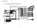
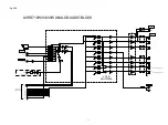
Страница 144: ...NJU72340AFH3 DIGITAL_ANALOG IC821 NJU72340A Terminal Functions 144 ...
Страница 147: ...2 FL DISPLAY FLD 018BT021GINK FRONT FL101 PIN CONNECTION GRID ASSIGNMENT 147 ...
Страница 148: ...ANODE CONNECTION 148 ...
Страница 168: ...EXPLODED REF No Part No Part Name Remarks Q ty New Ver S14 nsp SCREW CTW3 6JR VTW3 6JR 2 20 ...


