


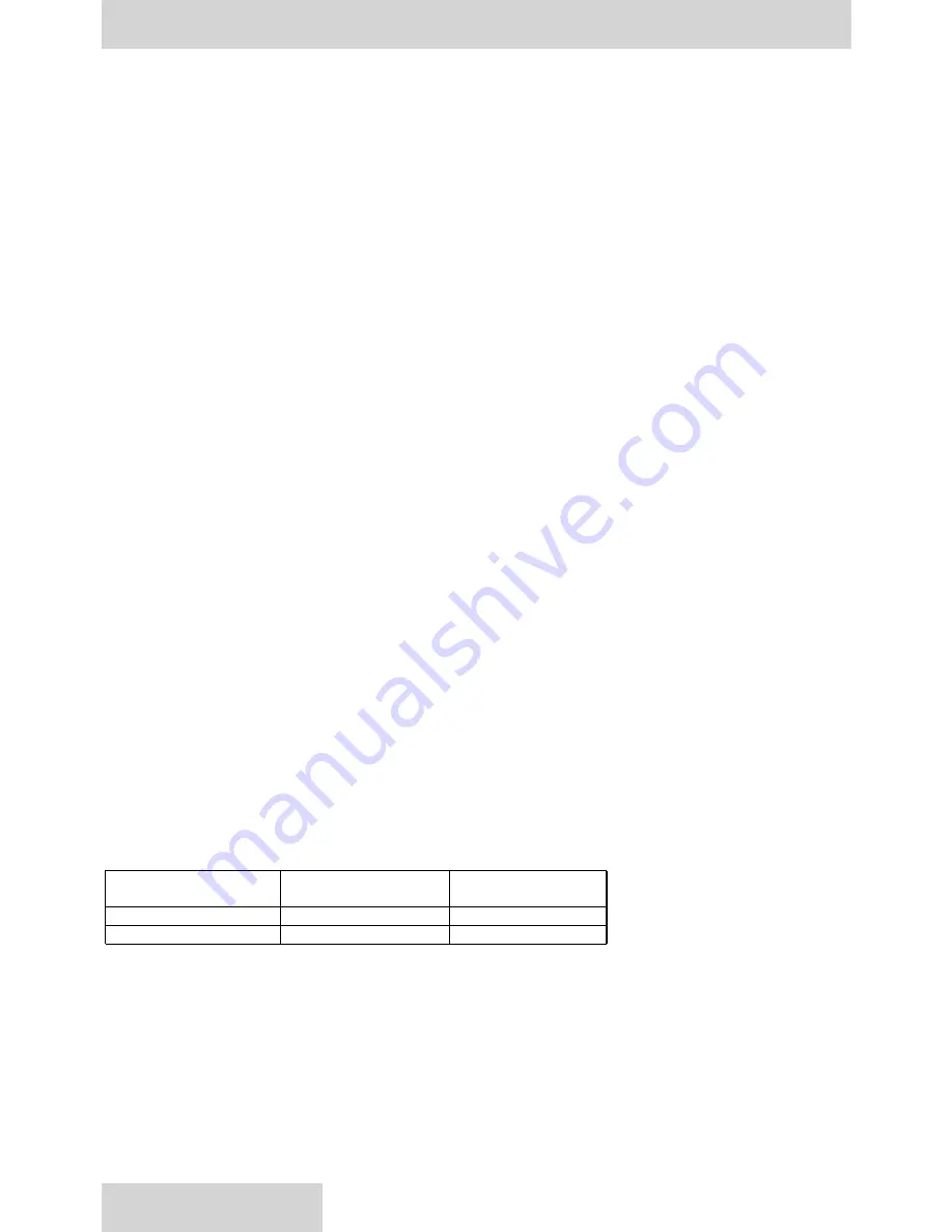
REWORK LIMITS OF WEAR PARTS
maximum rework
minimum dimension
item
from original dimension
after rework
wear plate
.0
05
", 0,
127
mm
.
184
",
4.674
mm
piston shoe face(pocket)
*
.4175", 10,605 mm
*shoe face pocket depth must be .004”, 0,10 mm minimum
WEAR PLATE
The wear plate finish must be 10
µ
in., 0,25
µ
m minimum, flat within .0005", 0,0127 mm and parallel to the backside
within .001", 0,0254 mm total indicator reading.
PISTON SHOE
The piston shoe wear face finish must be 45
µ
in., 1,143
µ
m min, and must be lapped in a set with the retainer plate. All
shoe sole thicknesses to be within .001", 0,0254 mm after lapping. The maximum permissible shoe and piston axial
looseness is .010", 0,254 mm.
Disassembly
Disassemble only as far as necessary to replace or repair worn parts.
If the pump has a rear drive, the mounting adapter and coupling must be removed prior to pump disassembly
Refer to
figure 3 page 16.
Clean outside surface of the pump before disassembly. Disassembly area should be clean. A suitable surface should
be used capable of supporting the pump weight of 177 lbs, 80,3 Kg.
Refer to illustration, see figure 1 and 2
1. Remove plug (49) and drain oil from pump. Position pump with shaft up.
2. Wind maximum volume screw CW (ref item (50), item 1 page 27) so that piston (44) bottoms out. This positions the
cam at approximately zero displacement allowing removal of the drive shaft.
3. Remove socket head cap screws (9). If disassembling PQ Control version, remove tubing and pass thru fitting (56).
4. Remove cradle assembly (6) from the housing. The threaded hole in end of the shaft is provided for lifting
this assembly. Threaded hole is 3/8-16 for P07, M10 for ISO and M12 for DIN shaft.
5. Remove snap ring (4).
6. Remove screws (47) to remove cam bearing (42).
7. Remove shaft (1), bearing, and seal retainer. Support flat face of the rocker cradle and press end of shaft opposite
the bearing end.
8. Remove the shaft seal (1c) from the retainer (1e) if necessary.
9. Remove retaining ring (20).
10.Press bearing off shaft if necessary. Press against bearing inner race.
11. If pump contains a volume indicator assembly (52):
Refer to. Figure 2
: Remove indicator pointer (2), retaining ring
(9) and pivot nut (1) from pump housing. Remove pivot shaft and fork assembly (3) and (4) through the hole.
11. Remove two screws (34), two washers (25), clearance bearing (24), and two washers (23) from retainer (28).
12.Wind maximum volume screw CCW until piston (44) bottoms out.
13.Remove control cap (50) and control cap (31). (
Refer to controls section for control disassembly).
14.The piston must be moved outward (away from pump center) to remove cam assembly.
15.Lift cam assembly (10) from pump. (Link (43), pistons and shoes and retainer plate(17), wear plate (22), and hold-
down (45 and 46) are part of the cam assembly.)
16.Remove slide link (43), retaining ring (45), thrust washer (46), pistons, shoes & retainer assembly (17) and wear
plate (22). The pins for the slide link and for the indicator have been pressed into the rocker cam and should not be
removed.
17.Remove two screws (26), and two retainers (28).
18.Remove Belleville washers (18) and barrel stop (19).
19.Attach tool (T-1) (pg. 76) to barrel assembly (14-1). (Two M6 screws are required.) Lift barrel from port plate and
housing.
20.The inner race of bearing (11) has a light press fit with barrel. Do not remove the inner race unless bearing needs
to be replaced. If replacement is necessary, remove seven socket head cap screws (12). Replace with 5/16-18
UNC x 6 1/2 in. long soc hd cap screws. Rest assembly on the extended screws. Press barrel from inner race.
Care must be taken to avoid damage to barrel face.
21.Remove port plate ref. see item (14), and alignment pin (16), from port block.
The barrel bearing outer race (11) should only be removed from housing if worn, damaged or closer inspection is
needed. A bearing puller should be used for removal.
DISASSEMBLY INSTRUCTIONS
11
www.comoso.com
Содержание P07 C-mod
Страница 12: ...PUMP PARTS LISTS 12 Ref Figure 1 Exploded view of pump with pressure compensator control www comoso com ...
Страница 54: ...PQ HIGH RESPONSE CONTROL 54 PQ CONTROL IN PROCESS OF DEVELOPMENT www comoso com ...
Страница 55: ...PQ HIGH RESPONSE CONTROL 55 PQ CONTROL IN PROCESS OF DEVELOPMENT www comoso com ...
Страница 56: ...PQ HIGH RESPONSE CONTROL 56 PQ CONTROL IN PROCESS OF DEVELOPMENT www comoso com ...
Страница 57: ...PQ HIGH RESPONSE CONTROL 57 PQ CONTROL IN PROCESS OF DEVELOPMENT www comoso com ...
Страница 74: ...74 TEST PROCEDURE PQ CONTROL IN PROCESS OF DEVELOPMENT www comoso com ...