9
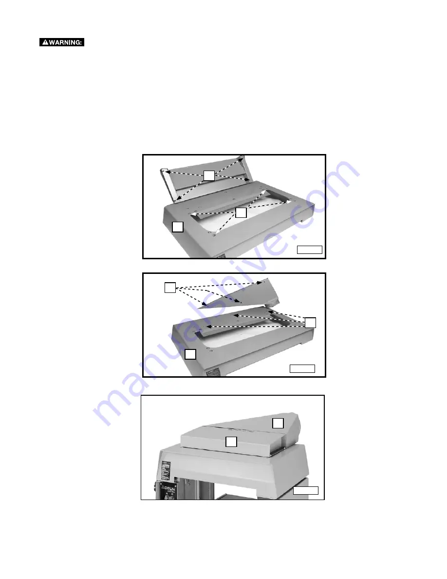
1. Remove the four screws and washers at (A) Fig. 6.
2. Place the guard on the planer cover (C) so that the holes in the guard (B) align with the holes in the cover (C).
3. Replace the screws and washers removed in
Step 1.
4. Remove the three screws (E) Fig. 7 on the planer cover (C).
5. Place the dust chute on the cover so that the holes in the dust chute (D) align with the holes in the cover (C).
6. Replace the screws and washers removed in
Step 4.
7. Arrange the cutterhead guard (B) Fig. 8 and dust chute (D) as shown in 8.
A
B
C
E
C
D
D
B
Fig. 8
Fig. 7
Fig. 6
ATTACHINg THE CUTTERHEAD gUARD AND THE DUST CHUTE
To reduce the risk of injury, turn unit off and disconnect it from power source before installing and
removing accessories, before adjusting or when making repairs.
An accidental start-up can cause injury.
Содержание 22-610
Страница 63: ...63 NOTES NOTAS ...


