15
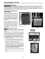
TO CHECk THE OUTFEED ROLLER HEIgHT SETTINg:
1. Use a feeler gauge (H) Fig. 26 to measure the gap between the table surface and the straight edge (C) near the
outfeed roller (E).
2. To adjust, loosen the jam nut (K) Fig. 27, located on the left side of machine under the table. Turn the collar (L)
right or left until the adjustment is correct.
3. Tighten the jam nut (K) Fig. 27.
C
H
E
k
L
Fig. 26
Fig. 27
ADJUSTINg THE PRESSURE BAR
IMPORTANT:
The pressure bar was set at the factory and should not need adjusting. However, when you sharpen or
replace the knives, check the pressure bar.
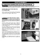
The pressure bar is located directly behind the cutterhead. It rides on the planed surface of the workpiece, pressing
the workpiece down on the table. If the workpiece does not feed, the pressure bar is set too low. If the workpiece has
chatter marks, the pressure bar is set too high. The pressure bar must be parallel to the knives and set .040" below
the cutting circle.
TO CHECk AND ADJUST THE PRESSURE BAR:
To reduce the risk of injury, turn unit off and disconnect it from power source before installing and
removing accessories, before adjusting or when making repairs.
An accidental start-up can cause injury.
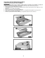
1. Remove the four screws that attach the top cover (A) Fig. 28 to the planer and carefully remove the top cover.
2. Check the knives for proper adjustment. (See
ADJUSTINg THE kNIVES).
3. Rotate the cutterhead until the knives are at their lowest point.
4. Place the gauge block (A) Fig. 29 on the table directly beneath the cutterhead. Place a .040" feeler gauge (B) Fig.
29 on top of the gauge block. Raise the table until
the knife (C) barely touches the feeler gauge.
5. Remove the feeler gauge. Move the gauge block
(A) Fig. 30 directly beneath the pressure bar (B) on
one end of the table. The pressure bar (B) should
just touch the gauge block (A). Check the pressure
bar at the opposite end of the table in the same
manner.
A
B
A
C
A
B
Fig. 28
Fig. 29
Fig. 30
Содержание 22-610
Страница 63: ...63 NOTES NOTAS ...


