background image

Back to Contents Page


Card Fan and Guide 

 Dell Precision 650 Computer 

Dell Precision™ Workstation 650 and Dell Precision Workstation 450 Service Manual


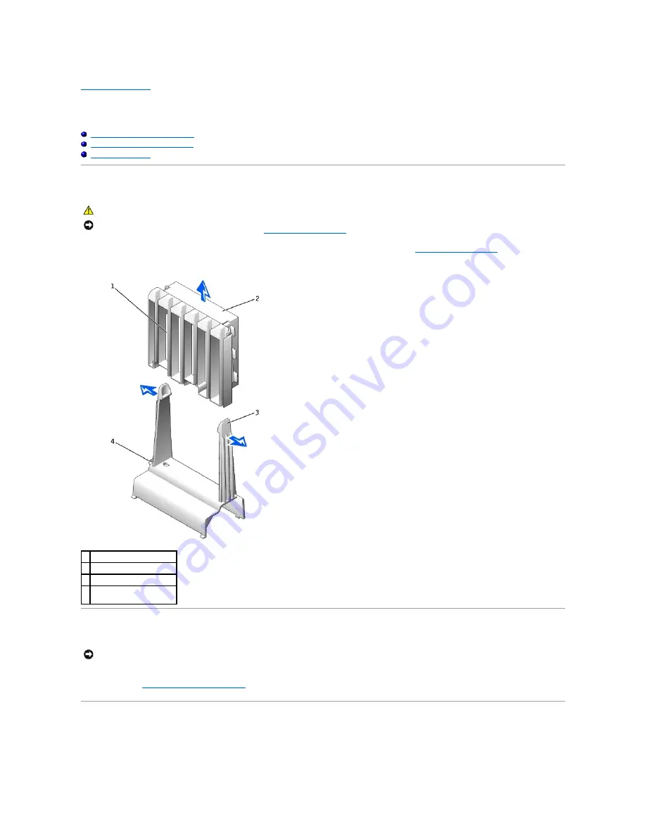
Removing the Card Fan and Guide


Replacing the Card Fan and Guide


The Card Fan Guide


Removing the Card Fan and Guide 

1.


Disconnect the fan power cable from its connector on the system board. To locate this connector, see "

System Board Components

." 


2.


Press the release tabs outward from the card fan guide, and lift the fan up and out of the guide. 


Replacing the Card Fan and Guide 

Insert the bottom of the fan into the clips on the card fan guide. Then press the top of the fan toward the card fan guide until the tabs on the card fan guide 
grasp the fan. See "

Removing the Card Fan and Guide

." 

The Card Fan Guide 

If you need to remove the card fan guide, pull up on the card-fan guide-release button and slide the guide up and out of the computer. To replace the card fan 
guide, insert the card-fan guide anchor tabs into the slots on the computer and slide the guide into position. 

CAUTION: 

Before you begin any of the procedures in this section, follow the safety instructions in the 

System Information Guide

.

NOTICE: 

Before disconnecting a device from the computer or removing a component from the system board, verify that the standby power light on the 

system board has turned off. To locate this light, see "

System Board Components

."

1  card fan guide 

2  card fan 

3  release button (2) 

4  card-fan guide-release 

button 

NOTICE: 

Ensure that the fan is properly installed on the guide. When the fan is properly installed, the fan manufacturer label faces the expansion-card 

guide, and the fan power cable extends toward the system board.

Содержание Precision Workstation 650

Страница 1: ...e Door Drives Dell Precision 450 Computer Overview Hard Drive Floppy Drive CD DVD Drive Cards Installing a Card Removing a Card Card Fan and Guide Dell Precision 650 Computer Removing the Card Fan and Guide Replacing the Card Fan and Guide The Card Fan Guide Memory Memory Installation Guidelines Removing a Memory Module Adding a Memory Module Microprocessor Airflow Shroud Dell Precision 650 Comput...

Страница 2: ...ell Precision 650 computer see System Board Components or see the system board label inside your computer 2 Remove the battery by carefully prying it out of its socket with your fingers or with a blunt nonconducting object such as a plastic screwdriver 3 Insert the new battery into the socket with the side labeled facing up and snap the battery into place 4 Close the computer cover and plug your c...

Страница 3: ......

Страница 4: ...sconnecting this type of cable press in on the locking tabs before disconnecting the cable As you pull connectors apart keep them evenly aligned to avoid bending any connector pins Also before you connect a cable ensure that both connectors are correctly oriented and aligned l Handle components and cards with care Do not touch the components or contacts on a card Hold a card by its edges or by its...

Страница 5: ...ting a sensitive component first place it in an antistatic container or packaging l Handle all sensitive components in a static safe area If possible use antistatic floor pads and workbench pads Back to Contents Page ...

Страница 6: ...nformation on configuring the card making internal connections or otherwise customizing it for your computer 5 Place the card in the connector and press down firmly Ensure that the card is fully seated in the slot If the card is full length insert the end of the card into the card guide bracket as you lower the card toward its connector on the system board Insert the card firmly into the card conn...

Страница 7: ...lignment guide Press the arm into place securing the card s in the computer 7 If you are replacing an AGP card align the AGP card guide with the base and press down on the indentation until the guide stops at the top of the AGP card 1 fully seated card 2 not fully seated card 3 bracket within slot 4 bracket caught outside of slot 1 filler bracket 2 alignment bar 3 alignment guide 4 retention arm ...

Страница 8: ...en change the setting for Network Interface Card to Off b Connect the network cable to the add in network connector s connectors Do not connect the network cable to the integrated connector on the back panel 12 Install any drivers required for the card as described in the card documentation Removing a Card 1 Press the lever on the card retention arm and raise the retention arm see Installing a Car...

Страница 9: ...up select Integrated Devices and then change the setting for Sound to On b Connect external audio devices to the audio connectors on the computer back panel 10 If you removed an add in network connector enter system setup select Integrated Devices and then change the setting for Network Interface Card to Off 11 Connect the network cable to the integrated connector on the computer back panel Back t...

Страница 10: ... 5 Lift both the chassis intrusion switch and the switch cable away from the computer Dell Precision 650 Computer Dell Precision 450 Computer CAUTION Before you begin any of the procedures in this section follow the safety instructions in the System Information Guide NOTICE Before disconnecting a device from the computer or removing a component from the system board verify that the standby power l...

Страница 11: ...Replacing the Chassis Intrusion Switch To replace the chassis intrusion switch perform the removal procedure in reverse Back to Contents Page ...

Страница 12: ...ll Precision 450 computer see System Board Components 4 Remove the mounting screw from the control panel 5 Lift the control panel away from the computer Dell Precision 650 Computer CAUTION Before you begin any of the procedures in this section follow the safety instructions in the System Information Guide 1 control panel connector 2 alignment hole 3 hard drive access light 4 power button 5 screw h...

Страница 13: ...recision 450 Computer Replacing the Control Panel To replace the control panel perform the removal procedure in reverse Back to Contents Page 1 control panel 2 mounting screw 1 control panel 2 mounting screw ...

Страница 14: ... the System Information Guide CAUTION To avoid electrical shock always unplug your computer from the electrical outlet before opening the cover NOTICE Be careful when opening the computer cover to ensure that you do not accidentally disconnect cables from the system board 1 CD DVD drive 6 microprocessor airflow shroud 2 floppy drive 7 security cable slot 3 hard drive 8 system board 4 power supply ...

Страница 15: ...M light STR_LED 18 microprocessor and heat sink connector CPU_1 6 power connector POWER 2 19 front panel audio connector FP2AUDIO 7 power connector POWER 1 20 microprocessor and heat sink connector CPU_0 8 USB connector USB 21 microprocessor fan connector FAN_P1 9 hard drive connector IDE1 22 microprocessor fan connector FAN_P0 10 real time clock reset jumper RTCRST 23 battery socket BATTERY 11 pa...

Страница 16: ... cable is the secondary slave device drive 1 See the drive documentation in your upgrade kit for information on configuring devices for the cable select setting Since cable select is the default setting any additional drives that are installed do not need to be set as a primary or secondary drive Your computer supports up to two IDE devices Hard drives should be connected to the connector labeled ...

Страница 17: ...SCSI devices installed by Dell are configured correctly during the manufacturing process You do not need to set the SCSI ID for these SCSI devices If you attach additional optional SCSI devices see the documentation for each device for information about setting the appropriate SCSI ID number Device Termination 1 power cable 2 power input connector 1 interface connector 2 colored stripe on cable 3 ...

Страница 18: ...to Auto l You may need to use programs other than those provided with the operating system to partition and format SCSI hard drives See the documentation that came with your SCSI software drivers for information on installing the appropriate drivers and preparing your SCSI hard drive for use SCSI Cables Ultra 320 optional on the Dell Precision 450 computer Ultra 160 m and Ultra2 Wide LVD drives ty...

Страница 19: ...h rail to the drive Attach the bracket rails to the new drive by aligning the screw holes on the drive with the screw holes on the bracket rails and then inserting and tightening all four screws two screws on each rail 4 Gently slide the drive into place until the tabs securely click into position 1 tabs 2 2 hard drive 1 drive 2 bracket rails 2 3 screws 4 NOTE If you are installing a hard drive in...

Страница 20: ...mentation that came with the drive for instructions on installing any software required for drive operation 10 If the drive you just installed is the primary drive insert a bootable floppy disk into drive A 11 Turn on the computer 12 Enter system setup and update the your drive configuration 13 After you have updated the system settings exit system setup and restart the computer 14 Partition and l...

Страница 21: ...Removing a Floppy Drive 1 Disconnect the power and floppy drive cables from the back of the floppy drive 2 Press inward on the two tabs on the sides of the drive slide the drive upward and remove it from the floppy drive bay CAUTION Before you begin any of the procedures in this section follow the safety instructions in the System Information Guide 1 power cable 2 floppy drive cable 3 floppy drive...

Страница 22: ... each rail to the drive Attach the bracket to the new drive by aligning the screw holes on the drive with the screw holes on the bracket rails and then inserting and tightening all four screws two screws on each rail 2 Gently slide the drive into place until the tabs securely click into position 3 Attach the power and floppy drive cables to the floppy drive 1 drive 2 bracket rails 2 3 screws 4 ...

Страница 23: ...m setup and update the appropriate Diskette Drive A option to reflect the size and capacity of your new floppy drive 9 To verify that your computer works correctly run the Dell Diagnostics CD DVD Drive Removing a CD DVD Drive 1 Disconnect the power and CD DVD drive cables from the back of the drive 2 Press inward on the two tabs on the sides of the drive and then slide the drive upward and remove ...

Страница 24: ...r If a set of rails is not attached inside the cover contact Dell 3 If you are installing a replacement drive and the new drive does not have the bracket rails attached remove the rails from the old drive by removing the two screws that secure each rail to the drive Attach the bracket to the new drive by aligning the screw holes on the drive with the screw holes on the bracket rails and then inser...

Страница 25: ...adding a drive that has an audio cable connect the audio cable to the audio connector on the system board 7 If you are installing a new CD DVD drive rather than replacing a drive remove the front panel inserts From inside the drive bay gently press on each side of the insert until it pops out 8 Check all cable connections and fold cables out of the way to provide airflow for the fan and cooling ve...

Страница 26: ...n 11 Update your configuration information by setting the appropriate Drive option 0 or 1 under Drives Secondary to Auto See Advanced Features in your User s Guide for more information 12 To verify that your computer works correctly run the Dell Diagnostics Back to Contents Page NOTICE To connect a network cable first plug the cable into the network wall jack and then plug it into the computer ...

Страница 27: ...pply securing slot on the computer ensuring that each securing tab is connected to its slot on the computer 2 Slide the power supply toward the back of the computer 3 Connect the power supply cables 4 Close the computer cover and restart the computer Back to Contents Page CAUTION Before you begin any of the procedures in this section follow the safety instructions in the System Information Guide N...

Страница 28: ...ual Removing the Drive Door Replacing the Drive Door Removing the Drive Door 1 Open the drive door 2 Unsnap the top hinge and pull the top of the drive door outward away from the computer CAUTION Before you begin any of the procedures in this section follow the safety instructions in the System Information Guide 1 top hinge 2 bottom hinge ...

Страница 29: ...3 Lift the bottom hinge away from the computer Replacing the Drive Door To replace the drive door perform the removal procedure in reverse Back to Contents Page ...

Страница 30: ...alling the Microprocessor Airflow Shroud 1 Attach both fan power cables to the connectors on the system board 2 Align the anchor tabs with the securing slots 3 Gently press the shroud until the anchor tabs snap securely into place 4 Close the computer cover 5 Connect your computer and devices to electrical outlets and turn them on Back to Contents Page CAUTION Before you begin any of the procedure...

Страница 31: ...Guide The Card Fan Guide If you need to remove the card fan guide pull up on the card fan guide release button and slide the guide up and out of the computer To replace the card fan guide insert the card fan guide anchor tabs into the slots on the computer and slide the guide into position CAUTION Before you begin any of the procedures in this section follow the safety instructions in the System I...

Страница 32: ...Back to Contents Page ...

Страница 33: ... panel by pressing each of the front panel release tabs The Dell Precision 650 computer has seven release tabs and the Dell Precision 450 computer has seven release tabs Dell Precision 650 Computer Dell Precision 450 Computer 3 Close the computer cover halfway and pull the front panel away from the computer Replacing the Front Panel To replace the front panel perform the removal procedure in rever...

Страница 34: ......

Страница 35: ...ore you begin any of the procedures in this section follow the safety instructions in the System Information Guide 1 front panel audio connector 7 diagnostic lights 4 2 control panel connector 8 IEEE 1394 connector 3 chassis intrusion switch connector 9 USB 2 0 connectors 2 4 system board connector 10 microphone connector 5 speaker connector 11 headphone connector 6 front panel USB IEEE 1394 conne...

Страница 36: ...bles that are connected to the front I O panel 5 From inside the cover remove the mounting screw that secures the front I O panel to the computer 6 Remove the front I O panel from the computer Dell Precision 650 Computer Dell Precision 450 Computer Replacing the I O Panel To replace the front I O panel perform the removal procedure in reverse Back to Contents Page 5 control panel connector ...

Страница 37: ......

Страница 38: ...ructions in the System Information Guide CAUTION To avoid electrical shock always unplug your computer from the electrical outlet before opening the cover NOTICE Be careful when opening the computer cover to ensure that you do not accidentally disconnect cables from the system board 1 floppy drive 5 padlock ring 2 CD DVD drive 6 microprocessor airflow shroud 3 hard drive 7 system board 4 power sup...

Страница 39: ...nd microprocessor only 6 power connector POWER 2 20 microprocessor and heat sink connector CPU_1 7 power connector POWER 1 21 front panel audio connector FP2AUDIO 8 front panel USB IEEE 1394 connector USB 22 microprocessor and heat sink connector CPU_0 9 hard drive connector IDE1 23 microprocessor fan connector FAN_P1 10 real time clock reset jumper RTCRST 24 microprocessor fan connector FAN_P0 11...

Страница 40: ...sure that the baffle is correctly positioned by guiding it into place as you lower the cover c Press down on the cover to close it d Once the cover is closed slide the release latch to the right until the latch clicks into place Dell Precision 650 Computer Dell Precision 450 Computer 4 If you are using a padlock to secure your computer install the padlock 1 cover release latch 2 security cable slo...

Страница 41: ...5 Connect your computer and devices to electrical outlets and turn them on Back to Contents Page ...

Страница 42: ...e touching anything inside your computer While you work periodically touch any unpainted metal surface on the computer to dissipate any static electricity that could harm internal components Dell Precision 650 Computer Dell Precision 450 Computer CAUTION Before you begin any of the procedures in this section follow the safety instructions in the System Information Guide CAUTION To guard against el...

Страница 43: ...Back to Contents Page 1 security cable slot 2 cover release latch 3 padlock ring ...

Страница 44: ...erly installed the diagnostic lights indicate an error l If you are upgrading your microprocessor keep your original microprocessor heat sink and securing clips for future troubleshooting Installing the Microprocessor 1 Remove the microprocessor airflow shroud for the Dell Precision 650 computer see Microprocessor Airflow Shroud Dell Precision 650 Computer or for the Dell Precision 450 computer se...

Страница 45: ...d for the Dell Precision 650 computer see Microprocessor Airflow Shroud Dell Precision 650 Computer or for the Dell Precision 450 computer see Microprocessor Airflow Shroud Dell Precision 450 Computer 2 Remove the microprocessor heat sink a Remove the two retention module clips by pressing the tabs together and lifting the retention module clips up b Press the lever on the retention module until t...

Страница 46: ... shroud for the Dell Precision 650 computer see Microprocessor Airflow Shroud Dell Precision 650 Computer or for the Dell Precision 450 computer see Microprocessor Airflow Shroud Dell Precision 450 Computer 6 Close the computer cover 7 Connect your computer and devices to electrical outlets and turn them on Back to Contents Page 6 lever NOTICE Be careful not to bend any of the pins when you remove...

Страница 47: ...ace cable is the secondary slave device drive 1 See the drive documentation in your upgrade kit for information on configuring devices for the cable select setting Since cable select is the default setting any additional drives that are installed do not need to be set as a primary or secondary drive Your computer supports up to two IDE devices Hard drives should be connected to the connector label...

Страница 48: ... SCSI controller card installed in your computer you have two separate SCSI buses operating Each SCSI bus has a set of SCSI ID numbers from 0 to 15 When SCSI devices are shipped from the factory the default SCSI ID numbers are assigned as follows SCSI devices installed by Dell are configured correctly during the manufacturing process You do not need to set the SCSI ID for these SCSI devices 1 powe...

Страница 49: ... a CD or tape drive Secondary Drive 0 and or Secondary Drive 1 should be set to Auto l You may need to use programs other than those provided with the operating system to partition and format SCSI hard drives See the documentation that came with your SCSI software drivers for information on installing the appropriate drivers and preparing your SCSI hard drive for use SCSI Cables Ultra 320 Ultra 16...

Страница 50: ... for your computer 3 If your replacement hard drive does not have the bracket rails attached remove the rails from the old drive by removing the two screws that secure each rail to the drive Attach the bracket rails to the new drive by aligning the screw holes on the drive with the screw holes on the bracket rails and then inserting and tightening all four screws two screws on each rail 1 power ca...

Страница 51: ... the controller card in an expansion slot See the documentation that accompanied the drive and controller card to verify that the configuration is correct for your computer 6 Connect the power and hard drive cables to the drive 1 drive 2 bracket rails 2 3 screws 4 NOTICE Match the colored strip on the cable with pin 1 on the drive pin 1 is marked as 1 ...

Страница 52: ...xit system setup and restart the computer 14 Partition and logically format your drive before you proceed to the next step See the documentation for your operating system for instructions 15 Test the hard drive by running the Dell Diagnostics 16 If the drive you just installed is the primary drive install your operating system on the hard drive Floppy Drive Removing a Floppy Drive 1 Disconnect the...

Страница 53: ...drive does not have the bracket rails attached remove the rails from the old drive by removing the two screws that secure each rail to the drive Attach the bracket to the new drive by aligning the screw holes on the drive with the screw holes on the bracket rails and then inserting and tightening all four screws two screws on each rail 1 power cable 2 floppy drive cable 1 tab 2 2 floppy drive ...

Страница 54: ...2 Gently slide the drive into place until the tabs securely click into position 3 Attach the power and floppy drive cables to the floppy drive 1 drive 2 bracket rails 2 3 screws 4 ...

Страница 55: ...tructions on installing any software required for drive operation 8 Enter system setup and update the appropriate Diskette Drive A option to reflect the size and capacity of your new floppy drive 9 To verify that your computer works correctly run the Dell Diagnostics CD DVD Drive Removing a CD DVD Drive 1 Disconnect the power and CD DVD drive cables from the back of the drive 1 power cable 2 flopp...

Страница 56: ...nstallation Check the documentation that accompanied the drive to verify that the drive is configured for your computer If you are installing an IDE drive configure the drive for the cable select setting 2 Connect the new drive to the set of rails that are attached to the inside of the cover If a set of rails is not attached inside the computer cover contact Dell 1 power cable 2 CD DVD drive cable...

Страница 57: ...crews two screws on each rail 4 Gently slide the drive into place until the tabs securely click into position 5 If you are installing a drive that has its own controller card install the controller card in an expansion slot See the documentation that accompanied the drive and controller card to verify that the configuration is correct for your computer 6 Connect the power and CD DVD drive cables t...

Страница 58: ...See the documentation that came with the drive for instructions on installing any software required for drive operation 11 Update your configuration information by setting the appropriate Drive option 0 or 1 under Drives Secondary to Auto See Advanced Features in your User s Guide for more information 12 Verify that your computer works correctly by running the Dell Diagnostics Back to Contents Pag...

Страница 59: ...uter cover 7 Connect your computer and devices to electrical outlets and turn them on Removing a VRM 1 Remove the microprocessor airflow shroud for the Dell Precision 650 computer see Microprocessor Airflow Shroud Dell Precision 650 Computer or for the Dell Precision 450 computer see Microprocessor Airflow Shroud Dell Precision 450 Computer 2 Press the securing clips at each end of the connector o...

Страница 60: ...d Dell Precision 450 Computer 6 Close the computer cover 7 Connect your computer and devices to electrical outlets and turn them on Back to Contents Page NOTICE To connect a network cable first plug the cable into the network wall jack and then plug it into the computer ...

Страница 61: ...2000 and Windows XP can only utilize a maximum of 4 GB of address space however the amount of memory available to the operating system is slightly less than 4 GB Certain components within the computer require address space in the 4 GB range Any address space reserved for these components cannot be used by computer memory The following is a list of components that require memory address space l Sys...

Страница 62: ...lips on the other sockets with memory modules installed 5 Close the computer cover 6 Connect your computer and devices to electrical outlets and turn them on The computer detects that the new memory does not match the existing configuration information and generates the following message The amount of system memory has changed Strike the F1 key to continue F2 to run the setup utility 7 Press F2 to...

Страница 63: ...sure that they are seated properly in their sockets Then repeat steps step 4 through step 7 10 When the System Memory total is correct press Esc to exit system setup 11 Run the Dell Diagnostics to verify that the memory modules are operating properly Back to Contents Page ...

Страница 64: ...essor Airflow Shroud 1 Insert the bottom anchor tabs into the anchor slots 2 Align and insert the side anchor tabs into the anchor slots 3 Press the indentations until the top anchor tabs on the shroud snap securely into place 4 Close the computer cover 5 Connect your computer and devices to electrical outlets and turn them on Back to Contents Page CAUTION Before you begin any of the procedures in...

Страница 65: ... the four securing slots in the computer 4 While pressing the power supply release button slide the power supply toward the back of the computer CAUTION Before you begin any of the procedures in this section follow the safety instructions in the System Information Guide NOTICE Before disconnecting a device from the computer wait 10 to 20 seconds after disconnecting the computer from its electrical...

Страница 66: ...uring tab is connected to its slot on the computer 3 Slide the power supply toward the front of the computer 4 Install the card fan guide a Place the card fan guide into the four securing slots in the computer b Slide the card fan guide to the left until it locks into position 5 Connect the power supply cables and the card fan cable 6 Replace the card fan 7 Install the cards 8 Close the computer c...

Страница 67: ...move the memory modules and install them on the replacement board b Remove the heat sink assembly and microprocessor from the existing system board and transfer them to the replacement system board 2 Configure the settings of the replacement system board 3 Set the jumpers on the replacement system board so they are identical to the ones on the existing board 4 Orient the replacement board by align...

Страница 68: ...5 Slide the system board assembly toward the back of the computer until the assembly clicks into position 6 Replace any components and cables that you removed from the system board Back to Contents Page ...

Отзывы: