background image

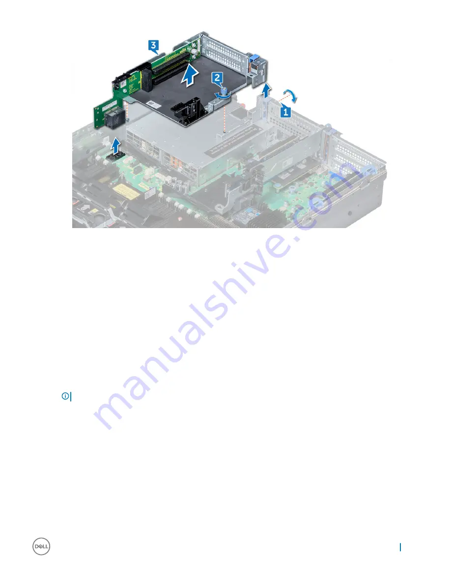
Figure 22. Removing expansion card riser 3

Installing expansion card riser 3

Steps

Align the following:

a Tab on the riser with the slot on the system and guide rails on the riser with the standoffs on the side of the system.
b Lower the riser into the system until the riser edge connector engages with the connector on the system board.

The riser card edge engages with the riser guide on the system.

Using Phillips #2 screwdriver, tighten the screw to secure the riser to the system.

Next steps

1

If removed, install expansion cards into the riser and connect any cable disconnected. 

2

If applicable, install the air shroud.

NOTE: 

If applicable, open the PCIe card holder latch on the air shroud to install the full length card.

3

Install any device drivers required for the card as described in the documentation for the card.

vFlash card – optional

Removing vFlash card

Prerequisites

1

If applicable, remove the full height PCIe card in expansion card riser 2.

2

If you are replacing the vFlash card, remove the micro SD cards.

Removing and installing components

57

Содержание Precision 7920 Rack

Страница 1: ...Dell Precision 7920 Rack Owner s Manual Regulatory Model E38S Regulatory Type E38S001 ...

Страница 2: ... to hardware or loss of data and tells you how to avoid the problem WARNING A WARNING indicates a potential for property damage personal injury or death Copyright 2017 Dell Inc or its subsidiaries All rights reserved Dell EMC and other trademarks are trademarks of Dell Inc or its subsidiaries Other trademarks may be trademarks of their respective owners 2017 10 Rev A00 ...

Страница 3: ...stalling components 15 Product Positioning 15 Recommended tools 16 Need to know 16 Common error messages 16 Startup Shutdown sequence 18 Diagnostics and indicators 19 Chassis LEDs 19 Status LED indicators 19 Hard drive indicator codes 20 NIC indicator codes 21 Power supply unit indicator codes 21 iDRAC Direct LED indicator codes 22 iDRAC Quick Sync 2 indicator codes 23 Enhanced Preboot System Asse...

Страница 4: ... Rails 69 Initialization 79 Basic configuration 80 Accessing system information by using QRL 81 Quick Resource Locator for 7920R 81 5 Technology and components 82 iDRAC9 82 iDRAC 9 New features 82 Dell Lifecycle Controller 83 iDRAC9 with Lifecycle Controller 83 Benefits of using iDRAC with Lifecycle Controller 83 Key features 84 Starting Lifecycle Controller 84 Processors 84 Processor features 85 ...

Страница 5: ...104 Integrated devices screen details 104 Serial Communication screen details 107 System profile settings screen details 107 System security settings screen details 108 Miscellaneous settings screen details 110 Technical specifications 110 System dimensions 110 Chassis weight 111 Processor specifications 111 PSU specifications 111 System battery specifications 112 Expansion bus specifications 112 ...

Страница 6: ...me as touching a connector on the back of the computer CAUTION Handle components and cards with care Do not touch the components or contacts on a card Hold a card by its edges or by its metal mounting bracket Hold a component such as a processor by its edges not by its pins CAUTION When you disconnect a cable pull on its connector or on its pull tab not on the cable itself Some cables have connect...

Страница 7: ...sure that you connect any external devices cards and cables before turning on your computer Steps 1 Replace the cover 2 If applicable install the system into the rack 3 Reconnect the peripherals and connect the system to the electrical outlet 4 Turn on the system including any attached peripherals Working on your computer 7 ...

Страница 8: ...stem health and system ID 3 iDRAC Quick Sync 2 wireless indicator 4 Hard drive x8 5 USB 3 0 connector 6 Optical drive optional 7 USB 2 0 connector 8 Power button Power light 9 VGA connector 10 USB management port iDRAC Direct 11 USB 2 0 connector 2 8 Chassis View ...

Страница 9: ...tification connector 12 System identification button Inside the system NOTE Many repairs may only be done by a certified service technician You should only perform troubleshooting and simple repairs as authorized in your product documentation or as directed by the online or telephone service and support team Damage due to servicing that is not authorized by Dell is not covered by your warranty Rea...

Страница 10: ...LCD panel provides system information status and error messages to indicate if the system is functioning correctly or requires attention The LCD panel can be used to configure or view the system s iDRAC IP address For more information about error messages see the Dell Event and Error Messages Reference Guide at Dell com openmanagemanuals OpenManage software The LCD panel is available only on the o...

Страница 11: ...u item highlighted by the cursor 3 Right Moves the cursor forward in one step increments During message scrolling Press and hold the right button to increase scrolling speed Release the button to stop NOTE The display stops scrolling when the button is released After 45 seconds of inactivity the display starts scrolling 4 LCD display Displays system information status and error messages or iDRAC I...

Страница 12: ... home Select the default information to be displayed on the Home screen See View menu section for the options and option items that can be set as the default on the Home screen View menu NOTE When you select an option in the View menu you must confirm the option before proceeding to the next action Option Description iDRAC IP Displays the IPv4 or IPv6 addresses for iDRAC9 Addresses include DNS Pri...

Страница 13: ...es contain information about Dell Precision 7920 Rack product overview System information label Precision 7920 Rack Front system information label Figure 3 LED Behavior Express Service Tag Configuration and Layout 3 Product Overview 13 ...

Страница 14: ...Precision 7920 Rack Service information Figure 4 System touchpoint electrical overview jumper settings and memory information 14 Product Overview ...

Страница 15: ...ce Performance Two Intel Xeon Skylake Processor Scalable Family processors Twenty four DIMM Slot supporting up total up to 1 5TB of memory Support total up to eight hard drives Availability Redundant power supply units PSUs Hot plug and hot swappable PSUs hard disk drives and fans PERC9 PERC10 Chipset SATA Internal vFLASH card iDRAC9 Express or Enterprise with Dell Lifecycle Controller Optional iD...

Страница 16: ...from boards Need to know Before you begin servicing the system you must read the following information Critical callouts Common error codes Version control for BIOS Firmware Software Startup Shutdown sequence Common error messages The Event Message Reference contains the error and event information generated by firmware and other agents that monitor system components These events might be logged p...

Страница 17: ...essage is logged in operating system logs Severity The classification of the event based on its impact to the platform or system The severity can be Severity 1 Critical Indicates a catastrophic production problem that might severely impact production systems or components or systems are down or not functioning Severity 2 Warning Indicates a high impact problem where a system or component is disrup...

Страница 18: ...feel through the boot process one exception the system will drop to text mode briefly to run legacy option ROMs when booting in legacy mode POST error messages are now compliant with Error Exception Message Initiative EEMI NOTE All POST error and warning messages will be logged in the LC log UEFI option ROMs display error warning messages on the screen via the Driver Health Protocol DHP The auto r...

Страница 19: ... error Check the System Event Log to determine if the drive has an error Run the appropriate Online Diagnostics test Restart the system and run embedded diagnostics ePSA If the drives are configured in a RAID array restart the system and enter the host adapter configuration utility program Temperature indicator The indicator turns solid amber if the system experiences a thermal error for example t...

Страница 20: ...ndicates whether the hard drive is currently in use or not The status LED indicator indicates the power condition of the drive Figure 5 Hard drive indicators 1 hard drive activity LED indicator 2 hard drive status LED indicator 3 hard drive NOTE If the hard drive is in the Advanced Host Controller Interface AHCI mode the status LED indicator does not turn on NOTE Drive status indicator behavior is...

Страница 21: ...r is green and activity indicator is blinking green The NIC is connected to a valid network at its maximum port speed and data is being sent or received Link indicator is amber and activity indicator is blinking green The NIC is connected to a valid network at less than its maximum port speed and data is being sent or received Link indicator is green and activity indicator is off The NIC is connec...

Страница 22: ...ismatch condition or failure to turn the system on CAUTION When correcting a PSU mismatch replace only the PSU with the blinking indicator Swapping the PSU to make a matched pair can result in an error condition and unexpected system shutdown To change from a high output configuration to a low output configuration or vice versa you must turn off the system CAUTION AC PSUs support both 240 V and 12...

Страница 23: ...ync 2 feature is turned off Press the iDRAC Quick Sync 2 button to turn on the iDRAC Quick Sync 2 feature If the LED fails to turn on reseat the left control panel flex cable and check If the problem persists see the Getting help section Solid white Indicates that iDRAC Quick Sync 2 is ready to communicate Press the iDRAC Quick Sync 2 button to turn off If the LED fails to turn off restart the sys...

Страница 24: ...em yourself service and support personnel can use the diagnostics results to help you solve the problem Dell Embedded system diagnostics NOTE The Dell Embedded System Diagnostics is also known as Enhanced Preboot System Assessment ePSA diagnostics The embedded system diagnostics provides a set of options for particular device groups or devices allowing you to Run tests automatically or in an inter...

Страница 25: ...th tab the Configuration tab and the Event Log tab 5 Close the Embedded System Diagnostics utility 6 To leave the diagnostics click Exit 7 Click OK when prompted and the system reboots Running the Embedded System Diagnostics from the Dell Lifecycle Controller To run the embedded system diagnostics from the Dell Lifecycle Controller Removing and installing components 25 ...

Страница 26: ...bout the jumpers It also provides some basic information about jumpers and switches and describes the connectors on the various boards in the system Jumpers on the system board help to disable the system and setup passwords You must know the connectors on the system board to install components and cables correctly 26 Removing and installing components ...

Страница 27: ...on 1 J_ODD Optical drive power connector 2 A7 A1 A8 A2 A9 A3 Memory module sockets 3 J_FAN2U_6 Cooling fan 6 connector 4 J_BP3 Backplane 3 power connector 5 J_FAN2U_5 Cooling fan 5 connector 6 A6 A12 A5 A11 A4 A10 Memory module sockets 7 J_FAN2U_4 Cooling fan 4 connector 8 INTRUSION_DET Intrusion switch connector Removing and installing components 27 ...

Страница 28: ...2 PCIe 225 W power 23 J_BATT_SIG NVDIMM N battery signal connector 24 J_BATT_PWR NVDIMM N battery power connector 25 J_USB_INT Internal USB connector 26 J_IDSDM IDSDM vFlash connector 27 J_NDC NDC connector 28 J_R2_X24_IT9 Riser 2 connector 29 J_R2_3R_X8_IT9 Riser 2 connector 30 BATTERY Battery connector 31 J_FRONT_VIDEO Video connector 32 J_R1_SS82_3 and J_R1_SS60_1 Riser 1 connector 33 J_TPM_MOD...

Страница 29: ...with your product Steps 1 Turn off the system including any attached peripherals and disconnect the system from the electrical outlet 2 Remove the system cover 3 Move the jumper on the system board jumper from pins 2 and 4 default to pins 4 and 6 4 Install the system cover The existing passwords are not disabled erased until the system boots with the jumper on pins 4 and 6 However before you assig...

Страница 30: ...using the key 3 Press the release button to release the bezel and pull the left end of the bezel 4 Unhook the right end and remove the bezel Installing the optional front bezel 1 Locate and remove the bezel key NOTE The bezel key is attached to the LCD bezel package 2 Align and insert the right end of the bezel onto the system 3 Press the release button and fit the left end of the bezel onto the s...

Страница 31: ...age from the slots on the system 3 Hold the cover on both sides and lift the cover away from the system Installing system cover Prerequisite 1 Ensure that all internal cables are routed correctly and connected and no tools or extra parts are left inside the system Steps 1 Align the tabs on the system cover with the slots on the system 2 Push the system cover latch down 3 Using a flat head screwdri...

Страница 32: ...t the optical drive cable from the optical drive 2 Press the blue latch and slide the optical drive from the system Next step Install the optical drive Installing optical drive 1 Slide the optical drive to the system until the locks into place 2 Connect the optical drive cable on the optical drive 3 Install system cover and front bezel if applicable 32 Removing and installing components ...

Страница 33: ... system Next step Install the shroud Installing air shroud Prerequisite 1 If applicable route the cables inside the system along the system wall and secure the cables by using the cable securing bracket Steps 1 Align the tabs on the air shroud with the slots on the system 2 Lower the air shroud into the system until it is firmly seated When firmly seated the memory socket numbers marked on the air...

Страница 34: ...tem 2 Lower the cooling fan assembly into the system until the cooling fan connectors engage with the connectors on the system board 3 Press the release levers to lock the cooling fan assembly into the system Cooling fans Removing cooling fan Prerequisites WARNING Opening or removing the system cover when the system is ON may expose you to a risk of electric shock Exercise utmost care while removi...

Страница 35: ... fan 1 Holding the release tab align the connector at the base of the cooling fan with the connector on the system board 2 Slide the cooling fan into the cooling fan assembly until the release tab locks into place Intrusion switch Removing intrusion switch Prerequisite 1 Remove the cooling fan assembly Step Press the intrusion switch and slide it out of the from the intrusion switch slot Removing ...

Страница 36: ...locks in place Next step 1 Install the cooling fan assembly Hard drive Removing hard drive blank Prerequisite 1 If installed remove the front bezel CAUTION To maintain proper system cooling all empty hard drive slots must have hard drive blanks installed Step Press the release button and slide the hard drive blank out of the hard drive slot 36 Removing and installing components ...

Страница 37: ...see the documentation for the storage controller CAUTION To prevent data loss ensure that your operating system supports hot swappable drive installation See the documentation supplied with your operating system CAUTION Before attempting to remove or install a hard drive while the system is running see the documentation for the storage controller card to ensure that the host adapter is configured ...

Страница 38: ...s hot swap drive installation See the documentation supplied with your operating system NOTE When a replacement hot swappable hard drive is installed and the system is powered on the hard drive automatically begins to rebuild Make absolutely sure that the replacement hard drive is blank or contains data that you wish to have over written Any data on the replacement hard drive is immediately lost a...

Страница 39: ... 5 inch hard drive from hard drive carrier Steps 1 Using Phillips 1 screwdriver remove the screws from the slide rails on the hard drive carrier 2 Lift the hard drive out of the hard drive carrier Next step Install hard drive into the hard drive carrier Removing and installing components 39 ...

Страница 40: ...ndicator flashes while the drive is turning off When the hard drive indicators are off the hard drive is ready for removal For more information see the documentation for the storage controller CAUTION To prevent data loss ensure that your operating system supports hot swappable drive installation See the documentation supplied with your operating system CAUTION Before attempting to remove or insta...

Страница 41: ...pports hot swap drive installation See the documentation supplied with your operating system NOTE When a replacement hot swappable hard drive is installed and the system is powered on the hard drive automatically begins to rebuild Make absolutely sure that the replacement hard drive is blank or contains data that you wish to have over written Any data on the replacement hard drive is immediately l...

Страница 42: ...install the front bezel Removing 2 5 inch hard drive from 3 5 inch hard drive carrier Steps 1 Using Phillips 1 screwdriver remove the screws from the slide rails on the 3 5 inch hard drive carrier and lift the hard drive 42 Removing and installing components ...

Страница 43: ...sembly and remove the hard drive Next step Install hard drive into the hard drive carrier Installing 2 5 inch hard drive into 3 5 inch hard drive carrier 1 Insert the 2 5 inch hard drive into the hard drive carrier and tighten the screws Removing and installing components 43 ...

Страница 44: ...5 inch hard drive carrier 3 Align the screw holes on the hard drive with the screws holes on the hard drive carrier Memory modules Removing memory modules Prerequisites 1 If applicable remove the air shroud 44 Removing and installing components ...

Страница 45: ...lignment key of the memory module socket and insert the memory module in the socket CAUTION Do not apply pressure at the center of the memory module apply pressure at both ends of the memory module evenly NOTE The memory module socket has an alignment key that enables you to install the memory module in the socket in only one orientation 4 Press the memory module with your thumbs until the socket ...

Страница 46: ... of the system 3 Set the module aside with processor side facing up Figure 13 Removing heat sink 2U Removing processor from processor heat sink module 1 Place the heat sink with the processor side facing up 2 Insert a flat blade screwdriver into the release slot marked with a yellow label Twist do not pry the screwdriver to break the thermal paste seal 3 Push the retaining clips on the processor b...

Страница 47: ...Installing processor into processor heat sink module Steps 1 Place the processor in the processor tray NOTE Ensure that pin 1 indicator on the CPU tray is aligned with the pin 1 indicator on the processor 2 Flex the outer edges of the bracket around the processor ensuring that the processor is locked into the clips on the bracket NOTE Ensure pin 1 indicator on the bracket is aligned with the pin 1...

Страница 48: ...ilateral design on the top of the processor CAUTION Applying too much thermal grease can result in excess grease coming in contact with and contaminating the processor socket NOTE The thermal grease syringe is intended for single use only Dispose the syringe after you use it Figure 15 Applying thermal grease on top of the processor 5 Place the heat sink on the processor and push down until the bra...

Страница 49: ...heat sink module on the processor socket CAUTION To avoid damaging the fins on the heat sink do not press down on the heat sink fins NOTE Ensure that the processor and heat sink is held parallel to the system board to prevent damaging the components 2 Push the blue retention clips inward to allow the heat sink to drop into place 3 Using the Torx T30 screwdriver tighten one screw at a time NOTE Ens...

Страница 50: ... riser Prerequisite 1 If applicable disconnect the cables from the expansion card Steps 1 Lift the expansion card latch out of the slot 2 Hold the expansion card by its edges and pull the card until the card edge connector disengages from the expansion card connector on the riser 50 Removing and installing components ...

Страница 51: ...Figure 17 Removing expansion card from expansion card riser 1 Figure 18 Removing expansion card from expansion card riser 2 Removing and installing components 51 ...

Страница 52: ...1 Unpack the expansion card and prepare it for installation NOTE For instructions see the documentation accompanying the card Steps 1 Lift the expansion card latch and remove the filler bracket 2 Hold the card by its edges and align the card edge connector with the expansion card connector on the riser 3 Insert the card edge connector firmly into the expansion card connector until the card is full...

Страница 53: ...ks Removing expansion card riser 1 Prerequisites 1 If installed remove expansion cards from the riser 2 Disconnect any cables connected to the riser card About this task NOTE If installing a replacement expansion card riser 1 make sure the VROC key is transfered from the old card to the new card Removing and installing components 53 ...

Страница 54: ...expansion card latch out of the slot 2 Hold the expansion card by its edges and pull the card until the card edge connector disengages from the expansion card connector on the riser 54 Removing and installing components ...

Страница 55: ...xpansion cards into the riser 2 Connect the cable which disconnected from the expansion card 3 Install any device drivers required for the card as described in the documentation for the card Removing expansion card riser 2 Prerequisites 1 If applicable remove the air shroud NOTE If applicable close the PCIe card holder latch on the air shroud to release the full length card 2 If installed remove e...

Страница 56: ...nnect any cable disconnected 2 If applicable install the air shroud NOTE If applicable open the PCIe card holder latch on the air shroud to install the full length card 3 Install any device drivers required for the card as described in the documentation for the card Removing expansion card riser 3 Prerequisites 1 If applicable remove the air shroud NOTE If applicable close the PCIe card holder lat...

Страница 57: ...river tighten the screw to secure the riser to the system Next steps 1 If removed install expansion cards into the riser and connect any cable disconnected 2 If applicable install the air shroud NOTE If applicable open the PCIe card holder latch on the air shroud to install the full length card 3 Install any device drivers required for the card as described in the documentation for the card vFlash...

Страница 58: ...system board 3 Push vFlash card until it is firmly seated on the system board Next step 1 If applicable install the full height PCIe card in expansion card riser 2 Network daughter card Removing network daughter card Prerequisite 1 Remove the expansion card riser 2 Steps 1 Using a Phillips 2 screwdriver loosen the captive screws that secure the Network Daughter Card NDC to the system board 2 Hold ...

Страница 59: ...ion card riser 2 Hard drive backplane Removing hard drive backplane Prerequisites CAUTION To prevent damage to the drives and backplane remove the hard drives from the system before removing the backplane CAUTION Note the number of each hard drive and temporarily label them before you remove the hard drive so that you can replace them in the same locations 1 Remove the air shroud 2 Remove the cool...

Страница 60: ... 1 Connect all the cables to the backplane 2 Install all the hard drives 3 Install the backplane cover 4 Install the cooling fan assembly 5 Install the air shroud Front USB module Removing front USB module Prerequisites 1 Remove the front bezel 2 Remove the system cover Steps 1 Unroute the cable and remove the screw that secures the USB module on the system 2 Push the cable and disconnect it from ...

Страница 61: ...SB memory key Steps 1 Locate the USB connector or USB key on the system board 2 If installed remove the USB key 3 Insert the new USB key into the USB connector Next step 1 While booting press F2 to enter the System Setup and verify that the USB key is detected by the system Power supply unit Removing power supply unit blank Install the power supply unit PSU blank only in the second PSU bay If you ...

Страница 62: ...ush it into the PSU slot until it clicks into place Removing AC power supply unit Prerequisite CAUTION The needs one power supply unit PSU for normal operation On power redundant systems remove and replace only one PSU at a time in a system that is powered on 1 Disconnect the power cable from the power source and from the PSU you intend to remove and then remove the cable from the strap on the PSU...

Страница 63: ...sure to create and safely store this recovery key If you replace this system board you must supply the recovery key when you restart your system or program before you can access the encrypted data on your hard drives CAUTION Do not attempt to remove the TPM plug in module from the system board Once the TPM plug in module is installed it is cryptographically bound to that specific system board Any ...

Страница 64: ...em board toward the front of the chassis disengages the connectors from the back of the chassis slots 3 Lift the system board out of the chassis Installing system board Steps 1 Unpack the new system board assembly CAUTION Do not lift the system board by holding a memory module processor or other components CAUTION Take care not to damage the system identification button while placing the system bo...

Страница 65: ... more information see the Entering the Service Tag section c Update the BIOS and iDRAC versions d Re enable the Trusted Platform Module TPM For more information see the Re enabling the Trusted Platform Module TPM section Trusted Platform Module Trusted Platform Module TPM is a dedicated microprocessor designed to secure hardware by integrating cryptographic keys into devices Software can use a TPM...

Страница 66: ... On the System Setup Main Menu screen click System BIOS System Security Settings 3 From the TPM Security option select On with Pre boot Measurements 4 From the TPM Command option select Activate 5 Save the settings 6 Restart your system 7 Enter System Setup again 8 On the System Setup Main Menu screen click System BIOS System Security Settings 9 From the Intel TXT option select On Control panel Re...

Страница 67: ...trol panel cable to the system board and secure it using cable latch 4 Using Phillips 1 screwdriver install the screws 6 that secure the control panel and cable tube to the system Next steps 1 If applicable install the cooling fan 1 2 Install air shroud Removing right control panel Prerequisites 1 Remove air shroud 2 Remove cooling fan assembly Steps 1 Disconnect the VGA cable from the system boar...

Страница 68: ... USB device into any of the USB ports on your system 3 Turn on your system 4 While booting press F11 to enter the Boot Manager 5 Go to System Utilities BIOS Update File Explorer and select the plugged in USB device 6 From the BIOS Update File Explorer select the BIOS update file The BIOS Update Utility with the current and new version of BIOS is displayed 7 Select Continue BIOS Update to install t...

Страница 69: ...g using System Setup About this task If you know the system service tag use the System Setup menu to enter the service tag 1 Turn on the system 2 To enter the System Setup press F2 3 Click Service Tag Settings 4 Enter the service tag NOTE You can enter the service tag only when the Service Tag field is empty Ensure that you enter the correct service tag Once the service tag is entered it cannot be...

Страница 70: ...hey will be installed Both the sliding rails and the static rails support tool less mounting in 19 wide EIA 310 E compliant square hole and unthreaded round hole 4 post racks Both also support tooled mounting in threaded hole 4 post racks but only the static rails as the more universal solution support mounting in 2 post Telco racks The table below shows the sliding and static rail configurations ...

Страница 71: ...he type of rack in which they are being mounted The Min Max values listed above represent the allowable distance between the front and rear mounting flanges in the rack Rail depth without the CMA represents the minimum depth of the rail with the outer CMA brackets removed if applicable as measured from the front mounting flanges of the rack Cable management arm CMA The optional cable management ar...

Страница 72: ...the system is installed vertically into the rails by inserting the standoffs on the sides of the system into the J slots in the inner rail members with the rails in the fully extended position As with all 2U systems a minimum of two people are required in order to properly install the system in the rails 1 Pull the inner rails out of the rack until they lock into place 72 Removing and installing c...

Страница 73: ...ate the rear rail standoff on each side of the system and lower them into the rear J slots on the slide assemblies 3 Rotate the system downward until all the rail standoffs are seated in the J slots Removing and installing components 73 ...

Страница 74: ... slots 4 Push the system inward until the lock levers click into place 5 Pull the blue slide release lock tabs forward on both rails and slide the system into the rack until the system is in the rack 74 Removing and installing components ...

Страница 75: ...il members must first be attached to the sides of the system and then inserted into the outer cabinet members installed in the rack 1 Pull the intermediate rails out of the rack until they lock into place 2 Release the inner rail lock by pulling forward on the white tabs and sliding the inner rail out of the intermediate rails Removing and installing components 75 ...

Страница 76: ...Rail component 1 Intermediate rail 2 Inner rail 3 Attach the inner rails to the sides of the system by aligning the J slots on the rail with the standoffs on the system and sliding forward on the system until they lock into place 76 Removing and installing components ...

Страница 77: ...Figure 29 Attach the inner rails to the system 4 With the intermediate rails extended install the system into the extended rails Removing and installing components 77 ...

Страница 78: ...Figure 30 Install system into the extended rails 5 Pull the blue slide release lock tabs forward on both the rails and slide the system into the rack 78 Removing and installing components ...

Страница 79: ...cable install the system into the rack Connect any peripherals to the system Connect the system to its electrical outlet Turn on the system by pressing the power button Turn on the attached peripherals Methods of setting up and configuring the iDRAC IP address You can set up the Integrated Dell Remote Access Controller iDRAC IP address by using one of the following interfaces 1 iDRAC Settings util...

Страница 80: ...racmanuals Basic configuration Once the system has been set up correctly users may perform further configurations such as operating system installation remote management and also drivers firmware installation Methods of installing the operating system You can install the supported operating system on the system if the system has been shipped without an operating system use the following methods De...

Страница 81: ... 5 Search by Category and click the System utilities HDD Zoning Configuration Utility is displayed Accessing system information by using QRL You can use the Quick Resource Locator QRL to get immediate access to the information about your system The QRL is located on the top of the system cover Prerequisites Ensure that your smartphone or tablet has the QR code scanner installed The QRL includes th...

Страница 82: ...gents It accomplishes this regardless of operating system or hypervisor presence or state iDRAC9 is available in the following variants iDRAC9 Basic available by default on all 200 500 series of rack or tower systems iDRAC9 Express available by default on all 600 and higher series of rack or tower systems and all blade systems iDRAC9 Enterprise available on all system models For more information s...

Страница 83: ...ions via iDRAC such as Online Capacity Expansion OCE and RAID Level Migration RLM without the use of agents via GUI or CLI Improved add delete of iDRAC Users Streamlined alerts configuration Added Power Control and Next Boot options in HTML5 vConsole Added feature Connection View provide the switch and port for iDRAC LOM s and Dell supported PCIe cards Internal 16GB vFlash card optional Bezel with...

Страница 84: ...n selected components of a system You can delete information pertaining to BIOS Lifecycle Controller logs iDRAC settings and storage components on the system However you cannot delete the iDRAC license information Security Support local key encryption Restoring the system Back up the system profile including RAID configuration and restore the system to a previously known state Importing a system l...

Страница 85: ... execution units processors which support Advanced RAS enable a 2nd FMA execution unit Supported Processors Table 15 Supported Processors for Precision 7920 Rack Model Intel SKU SKU type Dell DPN Speed GH z Cache M B QPI GT s Max Memory Speed M T s Cores Turbo TDP Intel Xeon Scalable Processor 3106 Bronze FH30X 1 7 24 75 9 6 2133 8 No Turbo 85W Intel Xeon Scalable Processor 3104 Bronze JNFW5 1 7 1...

Страница 86: ... Turbo 140W Intel Xeon Scalable Processor 6130 Gold XJ73T 2 1 22 10 4 2400 16 Turbo 125W Intel Xeon Scalable Processor 5120 Gold 7051X 2 2 19 25 10 4 2400 14 Turbo 105W Intel Xeon Scalable Processor 5118 Gold 4J8WW 2 3 16 5 10 4 2400 12 Turbo 105W Intel Xeon Scalable Processor 5115 Gold 9JV7H 2 4 13 75 10 4 2400 10 Turbo 85W Intel Xeon Scalable Processor 8180 Platinum K2XNJ 2 5 38 5 10 4 2666 28 T...

Страница 87: ... Rack will function normally if there is just a single processor placed in the CPU1 socket However CPU and memory blank associated with CPU2 are required to be populated for thermal reasons The system will not boot if only CPU2 socket is populated With single CPU configuration all three PCIe slots in Riser 1C and PCIe slot 6 in Riser 2A will be functional Chipset The Precision 7920 Rack systems us...

Страница 88: ...g frequency can be 2133 MT s 2400 MT s or 2666 MT s depending on the following factors DIMM type RDIMM or LRDIMM Number of DIMMs populated per channel System profile selected for example Performance Optimized Custom or Dense Configuration Optimized Maximum supported DIMM frequency of the processors Your system contains 24 memory sockets split into two sets of 12 sockets one set per processor Each ...

Страница 89: ... installed they will operate at the speed of the slowest installed memory module s or slower depending on the system DIMM configuration Populate memory module sockets only if a processor is installed For single processor systems sockets A1 A12 are available For dual processor systems sockets A1 to A12 and sockets B1 to B12 are available Populate all the sockets with white release tabs first follow...

Страница 90: ...x4 All Modes 1 2 Memory Speed The Precision 7920 Rack supports memory speeds of 2666 MT s 2400 MT s and 2133 MT s depending on the DIMM types installed and the configuration All memory on all processors and channels run at the same speed and voltage By default this speed will be the highest speed supported by the CPU and the DIMMs The operating speed of the DIMMs is also determined by the maximum ...

Страница 91: ...ing help section The LCD backlight remains off if LCD messaging is turned off using the iDRAC utility the LCD panel or other tools Figure 32 LCD panel features Table 21 LCD panel features Item Button or display Description 1 Left Moves the cursor back in one step increments 2 Select Selects the menu item highlighted by the cursor 3 Right Moves the cursor forward in one step increments During messa...

Страница 92: ...the Home screen View menu NOTE When you select an option in the View menu you must confirm the option before proceeding to the next action Option Description iDRAC IP Displays the IPv4 or IPv6 addresses for iDRAC9 Addresses include DNS Primary and Secondary Gateway IP and Subnet IPv6 does not have Subnet MAC Displays the MAC addresses for iDRAC iSCSI or Network devices Name Displays the name of th...

Страница 93: ...eight Full Length x8 x16 Riser 3A Slot 8 Processor 2 Full Height Full Length x16 x16 NOTE The expansion card slots are not hot swappable The following table provides guidelines for installing expansion cards to ensure proper cooling and mechanical fit The expansion cards with the highest priority should be installed first using the slot priority indicated All the other expansion cards should be in...

Страница 94: ...de in slots 4 and 7 with a 2nd CPU installed An SLI cable must also be installed 7 Zoom4 Dual Zoom4 requires dual CPU and both Zoom cards must be populated on CPU2 slots 4 8 8 No Teradici P25 or P45 in slot 3 Storage The Precision 7920 Rack provide scalable storage that allows you to adapt to your workload and operational demands The Precision 7920 Rack offers storage expansion with the front hard...

Страница 95: ...Us will be put into sleep mode when system utilization is low in order to maximize efficiency NOTE If two PSUs are used they must be of the same maximum output power Hot spare feature Your system supports the hot spare feature that significantly reduces the power overhead associated with power supply unit PSU redundancy When the hot spare feature is enabled one of the redundant PSUs is switched to...

Страница 96: ...e TPM chip is on the Plug in Module PIM and bound only to one system board The system board has a connector for the plug in module and it is factory installed Figure 33 Trusted platform module There are four types of TPM chip options No TPM TPM 1 2 Nuvoton FIPS CC TCG TPM TPM 2 0 Nuvoton FIPS CC TCG TPM 2 0 NationZ NOTE In a scenario where both the control panel and system board are dispatched Del...

Страница 97: ...stem These settings have already been preconfigured per solution requirements Contact Dell before you change these settings NOTE Help text for the selected field is displayed in the graphical browser by default To view the help text in the text browser press F1 You can access system setup by using two methods Standard graphical browser The browser is enabled by default Text browser The browser is ...

Страница 98: ...essor Settings Displays information and options related to the processor such as speed cache size and so on SATA Settings Displays options to enable or disable the integrated SATA controller and ports NVMe Settings Displays options to enable or disable the NVMe Settings Boot Settings Displays options to specify the boot mode BIOS or UEFI Enables you to modify UEFI and BIOS boot settings Network Se...

Страница 99: ...are UEFI Compliance Version Displays the system firmware UEFI compliance level Memory settings screen details You can use the Memory Settings screen to view all the memory settings as well as to enable or disable specific memory functions such as system memory testing and node interleaving You can view the Memory Setting screen by clicking System Setup Main Menu System BIOS Memory Settings The Mem...

Страница 100: ...sables the additional hardware capabilities provided for virtualization By default the Virtualization Technology option is set to Enabled Adjacent Cache Line Prefetch Optimizes the system for applications that require high utilization of sequential memory access By default the Adjacent Cache Line Prefetch option is set to Enabled You can disable this option for applications that require high utili...

Страница 101: ... view the SATA settings of SATA devices and enable RAID on your system You can view the SATA Settings screen by clicking System Setup Main Menu System BIOS SATA Settings The SATA Settings screen details are explained below Menu Item Description Embedded SATA Enables the embedded SATA to be set to Off AHCI Mode or RAID Mode modes By default the Embedded SATA option is set to AHCI Mode Security Free...

Страница 102: ... Sets the drive type of the selected device Model Displays the drive model of the selected device Drive Type Displays the type of drive attached to the SATA port Capacity Displays the total capacity of the hard drive The field is undefined for removable media devices such as optical drives Port H Sets the drive type of the selected device Model Displays the drive model of the selected device Drive...

Страница 103: ...ystem Setup Main Menu System BIOS Boot Settings The Boot Settings screen details are explained as follows Menu Item Description Boot Mode Enables you to set the boot mode of the system CAUTION Switching the boot mode may prevent the system from booting if the operating system is not installed in the same boot mode NOTE Setting this field to UEFI disables BIOS Boot Settings menu Setting this field ...

Страница 104: ...t and IPv6 VLAN Enables or disables PXE device Options are Enabled and Disabled set default VLAN ID Displays the VLAN ID VLAN Priority Displays the VLAN Priority UEFI HTTP Settings This field enables the BIOS to create a UEFI boot option for the HTTP device Option is set to Disabled HTTP Device1 This field enables the BIOS to create a UEFI boot option for the HTTP device Option is set to Disabled ...

Страница 105: ...ust remain plugged into the GPU until the system is booted into the operating system with the driver loaded Once the system is booted into the operating system the monitor can be unplugged and then hot plugged The monitor will not be hot pluggable unless this process is followed DP cable can be hot plugged mDP cable can be hot plugged DVI cable can be hot plugged DP to VGA dongle cable cannot be h...

Страница 106: ...t Driver Enabled default Disabled Boot Driver Disabled 6 Slot 6 Boot Driver Enabled default Disabled Boot Driver Disabled Slot Bifurcation 1 Slot 1 Bifurcation x16 Bifurcation default 2 Slot 2 Bifurcation x4 Bifurcation x8 Bifurcation default 3 Slot 3 Boot Driver x4 Bifurcation x8 Bifurcation default 4 Slot 4 Boot Driver x16 Bifurcation default 5 Slot 5 Boot Driver x4 Bifurcation x8 Bifurcation de...

Страница 107: ...if the attempt fails and the value must not be changed By default the Failsafe Baud Rate option is set to 115200 Remote Terminal Type Sets the remote console terminal type By default the Remote Terminal Type option is set to VT 100 VT 220 Redirection After Boot Enables or disables the BIOS console redirection when the operating system is loaded By default the Redirection After Boot option is set t...

Страница 108: ...r better power savings Number of Turbo Boot Enabled Cores for Processor 1 NOTE If there are two processors installed in the system you see an entry for Number of Turbo Boost Enabled Cores for Processor 2 Controls the number of turbo boost enabled cores for processor 1 By default the maximum number of cores is all Monitor Mwait Enables the Monitor Mwait instructions in the processor By default the ...

Страница 109: ...ed selected UEFI variables are protected in the environment and new UEFI boot entries are forced to be at the end of the current boot order Secure ME PCI Cfg Space Enabled this setting will hide the PCU configuration space for the management engine ME HECI device and is set to Disabled by default Secure Boot Enables Secure Boot where the BIOS authenticates each pre boot image using the certificate...

Страница 110: ...sables the F1 F2 prompt on error By default F1 F2 Prompt on Error is set to Enabled The F1 F2 prompt also includes keyboard errors Load Legacy Video Option ROM Enables you to determine wether the system BIOS loads the legacy video INT 10H option ROM from the video controller Selecting Enabled in the operating system does not support UEFI video output standards This field is only for UEFI boot mode...

Страница 111: ...ves SSDs 3 5 inch hard drive systems 28 6 kg 63 05 lb Processor specifications The Precision 7920 Rack system supports up to two Intel Xeon scalable family processors PSU specifications The Precision 7920 Rack system supports up to two AC power supply units PSUs BIOS and UEFI 111 ...

Страница 112: ...ards that can be installed on the system board using expansion card risers The following table provides detailed information about the expansion card riser specifications Table 29 Expansion card riser configurations Expansion card riser PCIe slots on the riser Height Length Link CPU Riser 1C Slot 1 Full Height Full Length x16 CPU1 Slot 2 Full Height Full Length x8 CPU1 Slot 3 Full Height Half Leng...

Страница 113: ... 3 0 compliant port One USB 3 0 compliant port on the front panel One micro USB 2 0 compliant port in the front panel for iDRAC Direct Two USB 3 0 complaint ports on the back panel NIC ports The Precision 7920 Rack system supports up to four Network Interface Controller NIC ports on the back panel which are available in the following configurations Four RJ 45 ports that support different combinati...

Страница 114: ...0 x 1200 60 8 16 32 1680 x 1050 60 8 16 32 1920 x 1080 60 8 16 32 1920 x 1200 60 8 16 32 NOTE 1920 x 1080 and 1920 x 1200 resolutions are only supported in reduced blanking mode Environmental specifications NOTE For additional information about environmental measurements for specific system configurations see Dell com environmental_datasheets Table 32 Temperature specifications Temperature Specifi...

Страница 115: ... 36 Maximum altitude specifications Maximum altitude Specifications Operating 3048 m 10 000 ft Storage 12 000 m 39 370 ft Table 37 Operating temperature de rating specifications Operating temperature de rating Specifications Up to 35 C 95 F Maximum temperature is reduced by 1 C 300 m 1 F 547 ft above 950 m 3 117 ft 35 C to 40 C 95 F to 104 F Maximum temperature is reduced by 1 C 175 m 1 F 319 ft a...

Страница 116: ... dust Air must be free of conductive dust zinc whiskers or other conductive particles NOTE This condition applies to data center and non data center environments Corrosive dust Air must be free of corrosive dust Residual dust present in the air must have a deliquescent point less than 60 relative humidity NOTE This condition applies to data center and non data center environments Table 39 Gaseous ...

Страница 117: ...diagnostics results to help you solve the problem Dell Embedded System Diagnostics NOTE The Dell Embedded System Diagnostics is also known as Enhanced Pre boot System Assessment ePSA diagnostics The Embedded System Diagnostics provides a set of options for particular device groups or devices allowing you to Run tests automatically or in an interactive mode Repeat tests Display or save test results...

Страница 118: ... executing the tests on all the detected devices System diagnostic controls Menu Description Configuration Displays the configuration and status information of all detected devices Results Displays the results of all tests that are run System health Provides the current overview of the system performance Event log Displays a time stamped log of the results of all tests run on the system This is di...

Отзывы: