background image

CAUTION:

 When removing the processor, do not touch any of the pins inside the socket or allow any objects

to fall on the pins in the socket.

3. Gently lift the processor from the processor socket.

Installing the processor

Prerequisites

If you are replacing a component, remove the existing component before performing the installation procedure.

About this task

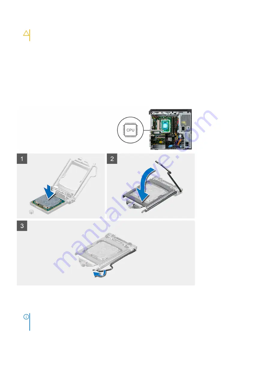
The following image indicates the location of the processor and provides a visual representation of the installation procedure.

Steps

1. Ensure that the release lever on the processor socket is fully extended in the open position.
2. Align the notches on the processor with the tabs on the processor socket and place the processor in the processor socket.

NOTE:

 The pin 1 corner of the processor has a triangle that aligns with the triangle on the pin 1 corner on the processor

socket. When the processor is properly seated, all four corners are aligned at the same height. If one or more corners of
the processor are higher than the others, the processor is not seated properly.

3. When the processor is fully seated in the socket, pivot the release-lever down and place it under the tab on the processor

cover.

38

Disassembly and reassembly

Содержание Precision 3650 Tower

Страница 1: ...Precision 3650 Tower Service Manual Regulatory Model D24M Regulatory Type D24M005 April 2021 Rev A00 ...

Страница 2: ...ential damage to hardware or loss of data and tells you how to avoid the problem WARNING A WARNING indicates a potential for property damage personal injury or death 2021 Dell Inc or its subsidiaries All rights reserved Dell EMC and other trademarks are trademarks of Dell Inc or its subsidiaries Other trademarks may be trademarks of their respective owners ...

Страница 3: ...the safety instructions that is shipped with the product or at www dell com regulatory_compliance CAUTION Before touching anything inside your computer ground yourself by touching an unpainted metal surface such as the metal at the back of the computer While you work periodically touch an unpainted metal surface to dissipate static electricity which could harm internal components CAUTION When you ...

Страница 4: ...wire ensure that it is connected to bare metal and never to a painted or non metal surface The wrist strap should be secure and in full contact with your skin and ensure that you remove all jewelry such as watches bracelets or rings prior to bonding yourself and the equipment Electrostatic discharge ESD protection ESD is a major concern when you handle electronic components especially sensitive co...

Страница 5: ...all and at a minimum test once per week A wrist strap tester is the best method for doing this test If you do not have your own wrist strap tester check with your regional office to find out if they have one To perform the test plug the wrist strap s bonding wire into the tester while it is strapped to your wrist and push the button to test A green LED is lit if the test is successful a red LED is...

Страница 6: ...re that no stray screws remain inside your computer 2 Connect any external devices peripherals or cables you removed before working on your computer 3 Replace any media cards discs or any other parts that you removed before working on your computer 4 Connect your computer and all attached devices to their electrical outlets 5 Turn on your computer 6 Working inside your computer ...

Страница 7: ...tity of screws and then place them in a screw storage box This is to ensure that the correct number of screws and correct screw type is restored when the component is replaced NOTE Some computers have magnetic surfaces Ensure that the screws are not left attached to such surface when replacing a component NOTE Screw color may vary with the configuration ordered Table 1 Screw list Component Screw t...

Страница 8: ... Graphics card 14 Optical drive Optional 15 Power supply unit Side cover Removing the side cover Prerequisites 1 Follow the procedure in before working inside your computer NOTE Ensure that you remove the security cable from the security cable slot if applicable About this task The following images indicate the location of the side cover and provide a visual representation of the removal procedure...

Страница 9: ...Disassembly and reassembly 9 ...

Страница 10: ... of the computer and lift the cover away from the computer Installing the side cover Prerequisites If you are replacing a component remove the existing component before performing the installation procedure About this task The following image indicates the location of the side cover and provides a visual representation of the installation procedure 10 Disassembly and reassembly ...

Страница 11: ...Steps 1 Locate the side cover slot on your computer Disassembly and reassembly 11 ...

Страница 12: ...se latch Next steps 1 Follow the procedure in after working inside your computer Power supply unit cage Opening the power supply unit cage Prerequisites 1 Follow the procedure in before working inside your computer 2 Remove the side cover About this task The following images indicate the location of the power supply unit cage and provide a visual representation of the removal procedure 12 Disassem...

Страница 13: ...e Closing the power supply unit cage Prerequisites If you are replacing a component remove the existing component before performing the installation procedure About this task The following images indicate the location of the power supply unit cage and provide a visual representation of the installation procedure Disassembly and reassembly 13 ...

Страница 14: ...14 Disassembly and reassembly ...

Страница 15: ...ollow the procedure in after working inside your computer Front bezel Removing the front bezel Prerequisites 1 Follow the procedure in before working inside your computer 2 Remove the side cover About this task The following images indicate the location of the front bezel and provide a visual representation of the removal procedure Disassembly and reassembly 15 ...

Страница 16: ...he computer chassis 3 Remove the front bezel from the computer Installing the front bezel Prerequisites If you are replacing a component remove the existing component before performing the installation procedure About this task The following image indicates the location of the front bezel and provides a visual representation of the installation procedure 16 Disassembly and reassembly ...

Страница 17: ...ow the procedure in after working inside your computer Memory modules Removing the memory modules Prerequisites 1 Follow the procedure in before working inside your computer 2 Remove the side cover 3 Open the PSU cage About this task The following images indicate the location of the memory modules and provide a visual representation of the removal procedure Disassembly and reassembly 17 ...

Страница 18: ...memory module slot Installing the memory modules Prerequisites If you are replacing a component remove the existing component before performing the installation procedure About this task The following image indicates the location of the memory modules and provides a visual representation of the installation procedure 18 Disassembly and reassembly ...

Страница 19: ...it Next steps 1 Close the PSU cage 2 Install the side cover 3 Follow the procedure in after working inside your computer Solid state drive Removing the M 2 2280 PCIe solid state drive Prerequisites 1 Follow the procedure in before working inside your computer 2 Remove the side cover 3 Open the PSU cage About this task The following images indicate the location of the solid state drive and provide ...

Страница 20: ...Installing the M 2 2280 PCIe solid state drive Prerequisites If you are replacing a component remove the existing component before performing the installation procedure About this task The following image indicates the location of the solid state drive and provides a visual representation of the installation procedure 20 Disassembly and reassembly ...

Страница 21: ...eps 1 Close the PSU cage 2 Install the side cover 3 Follow the procedure in after working inside your computer 2 5 inch hard drive Removing the 2 5 inch hard disk drive Prerequisites 1 Follow the procedure in before working inside your computer 2 Remove the side cover 3 Open the PSU cage About this task The following images indicate the location of the 2 5 inch hard disk drive assembly and provide...

Страница 22: ...assembly from the computer NOTE Note the orientation of the hard disk drive so that you can replace it correctly Installing the 2 5 inch hard disk drive Prerequisites If you are replacing a component remove the existing component before performing the installation procedure About this task The following image indicates the location of the 2 5 inch hard disk drive assembly and provides a visual rep...

Страница 23: ...lose the PSU cage 2 Install the side cover 3 Follow the procedure in after working inside your computer 3 5 inch hard drive Removing the 3 5 inch hard disk drive assembly Prerequisites 1 Follow the procedure in before working inside your computer 2 Remove the side cover 3 Open the PSU cage About this task The following images indicate the location of the 3 5 inch hard disk drive assembly and provi...

Страница 24: ...om the slots on the computer chassis 5 Lift the hard disk drive assembly from the computer NOTE Note the orientation of the hard disk drive so that you can replace it correctly Installing the 3 5 inch hard disk drive assembly Prerequisites If you are replacing a component remove the existing component before performing the installation procedure About this task The following image indicates the lo...

Страница 25: ...ve module 3 Insert the tab on the PCIe card holder into the slot on the chassis and gently press down until it is secured to the graphics card Next steps 1 Close the PSU cage 2 Install the side cover 3 Follow the procedure in after working inside your computer WLAN card Removing the WLAN card Prerequisites 1 Follow the procedure in before working inside your computer 2 Remove the side cover 3 Open...

Страница 26: ...the WLAN card 3 Disconnect the antenna cables from the WLAN card 4 Slide and remove the WLAN card from the connector on the system board Installing the WLAN card Prerequisites If you are replacing a component remove the existing component before performing the installation procedure About this task The following image indicates the location of the wireless card and provides a visual representation...

Страница 27: ...tenna cable color Main white triangle White Auxiliary black triangle Black 2 Place the WLAN card bracket to secure the WLAN antenna cables 3 Insert the WLAN card into the connector on the system board 4 Replace the M2x3 5 screw to secure the plastic tab to the WLAN card Next steps 1 Close the PSU cage 2 Install the side cover 3 Follow the procedure in after working inside your computer Disassembly...

Страница 28: ...pen the PSU cage About this task The following images indicate the location of the slim ODD and provide a visual representation of the removal procedure Steps 1 Disconnect the data and power cables from the slim ODD 2 Pull the securing tab to release the slim ODD from the chassis 3 Slide and remove the slim ODD from the ODD slot 28 Disassembly and reassembly ...

Страница 29: ...sert the slim ODD assembly into the ODD slot 2 Slide the slim ODD assembly until it snaps into place 3 Route the power cable and data cable through the routing guides and connect the cables to the slim ODD Next steps 1 Close the PSU cage 2 Install the side cover 3 Follow the procedure in after working inside your computer Graphics card Removing the graphics card Prerequisites 1 Follow the procedur...

Страница 30: ...release it from the slot on the chassis 4 Push and hold the securing tab on the graphics card slot and lift the graphics card from the graphics card slot Installing the graphics card Prerequisites If you are replacing a component remove the existing component before performing the installation procedure About this task The following images indicate the location of the graphics card and provide a v...

Страница 31: ...ntly press down until it is secured to the graphics card Next steps 1 Close the PSU cage 2 Install the side cover 3 Follow the procedure in after working inside your computer System fan Removing the system fan Prerequisites 1 Follow the procedure in before working inside your computer 2 Remove the side cover 3 Open the PSU cage About this task The following images indicate the location of the fan ...

Страница 32: ... Slide the system fan and bracket out of the computer Installing the system fan Prerequisites If you are replacing a component remove the existing component before performing the installation procedure About this task The following image indicates the location of the fan duct and provides a visual representation of the installation procedure 32 Disassembly and reassembly ...

Страница 33: ...inside your computer Coin cell battery Removing the coin cell battery Prerequisites 1 Follow the procedure in before working inside your computer 2 Remove the side cover 3 Open the PSU cage 4 Remove the powered GPU NOTE This step is required only if the system is configured with powered GPU About this task The following images indicate the location of the coin cell battery and provide a visual rep...

Страница 34: ... computer Installing the coin cell battery Prerequisites If you are replacing a component remove the existing component before performing the installation procedure About this task The following image indicates the location of the coin cell battery and provides a visual representation of the installation procedure 34 Disassembly and reassembly ...

Страница 35: ...oving the processor fan and heat sink assembly Prerequisites 1 Follow the procedure in before working inside your computer WARNING The heat sink may become hot during normal operation Allow sufficient time for the heat sink to cool before you touch it CAUTION For maximum cooling of the processor do not touch the heat transfer areas on the heat sink The oils in your skin can reduce the heat transfe...

Страница 36: ...at thermal conductivity is achieved About this task The following image indicates the location of the processor fan and heat sink assembly and provides a visual representation of the installation procedure Steps 1 Align the screw holes on the processor fan and heat sink assembly with the screw holes on the system board 2 Tighten the four captive screws that secure the processor fan and heat sink a...

Страница 37: ...ght still be hot after the computer is shut down Allow the processor to cool down before removing it About this task The following images indicate the location of the processor and provide a visual representation of the removal procedure Steps 1 Press down and push the release lever away from the processor to release it from the securing tab 2 Lift the lever upward to lift the processor cover Disa...

Страница 38: ...nsure that the release lever on the processor socket is fully extended in the open position 2 Align the notches on the processor with the tabs on the processor socket and place the processor in the processor socket NOTE The pin 1 corner of the processor has a triangle that aligns with the triangle on the pin 1 corner on the processor socket When the processor is properly seated all four corners ar...

Страница 39: ...power button cable out from the front side chassis of the computer 3 Pull the power button cable out from the computer Installing the power button Prerequisites If you are replacing a component remove the existing component before performing the installation procedure About this task The following images indicate the location of the power button switch and provide a visual representation of the in...

Страница 40: ... the removal procedure Steps 1 Disconnect the intruder cable from the connector on the system board 2 Slide and remove the intrusion switch from the chassis Installing the intrusion switch Prerequisites If you are replacing a component remove the existing component before performing the installation procedure About this task The following image indicates the location of the intrusion switch and pr...

Страница 41: ...er 3 Follow the procedure in after working inside your computer Front I O panel Removing the IO panel Prerequisites 1 Follow the procedure in before working inside your computer 2 Remove the side cover 3 Open the front bezel 4 Open the PSU cage About this task The following image indicates the location of the intrusion switch and provides a visual representation of the removal procedure Disassembl...

Страница 42: ...from the chassis Installing the IO panel Prerequisites If you are replacing a component remove the existing component before performing the installation procedure About this task The following image indicates the location of the intrusion switch and provides a visual representation of the installation procedure 42 Disassembly and reassembly ...

Страница 43: ...at secures the IO panel to the computer chassis 3 Connect the IO audio SD card USB Type C and IO USB cables to the connector on the system board Next steps 1 Close the PSU cage 2 Install the front bezel 3 Install the side cover 4 Follow the procedure in after working inside your computer Disassembly and reassembly 43 ...

Страница 44: ... board power connector 10 SD card connector 11 Front panel USB connector 12 Front panel USB C connector 13 Front panel USB power connector 14 Cion cell battery 15 SATA 0 blue SATA 1 white SATA 2 and SATA 3 black connectors 16 M 2 PCIe SSD connector 17 System fan connector front 18 Thunderbolt 4 AIC connector 19 E20 connector 20 E23 connector 21 CAC_PIV power connector 22 P30 connector 23 CMOS cloc...

Страница 45: ...ing the system board removes any changes that you have made to the BIOS using the BIOS setup program You must make the appropriate changes again after you replace the system board NOTE Before disconnecting the cables from the system board note the location of the connectors so that you can reconnect the cables correctly after you replace the system board 2 Remove the side cover 3 Remove the front ...

Страница 46: ...46 Disassembly and reassembly ...

Страница 47: ...an angle and remove the system board off the chassis Installing the system board Prerequisites If you are replacing a component remove the existing component before performing the installation procedure About this task The following images indicate the location of the system board and provide a visual representation of the installation procedure Disassembly and reassembly 47 ...

Страница 48: ... cell battery 4 Install the graphics card 5 Install the M 2 2280 SSD 6 Install the WLAN 7 Install the memory module 8 Close the PSU cage 9 Install the front bezel 10 Install the side cover 11 Follow the procedure in after working inside your computer NOTE Your computer s Service Tag is stored in the system board You must enter the Service Tag in the BIOS setup program after you replace the system ...

Страница 49: ...downloads Drivers and downloads When troubleshooting downloading or installing drivers it is recommended that you read the Dell Knowledge Based article Drivers and Downloads FAQ SLN128938 3 Drivers and downloads 49 ...

Страница 50: ...alled devices the items that are listed in this section may or may not appear Table 3 System setup options System information menu Overview Precision 3650 Tower BIOS Version Displays the BIOS version number Service Tag Displays the Service Tag of the computer Asset Tag Displays the Asset Tag of the computer Manufacture Date Displays the manufacture date of the computer Ownership Date Displays the ...

Страница 51: ...ory Displays the video memory information of the computer Wi Fi Device Displays the wireless device information of the computer Native Resolution Displays the native resolution of the computer Video BIOS Version Displays the video BIOS version of the computer Audio Controller Displays the audio controller information of the computer Bluetooth Device Displays the Bluetooth device information of the...

Страница 52: ...t address By default the COM1 Port is configured at 3F8h with IRQ4 option is enabled USB Configuration Enable or disable booting from USB mass storage devices through the boot sequence or boot menu By default all the options are enabled Front USB Configuration Enable or disable the individual front USB ports By default all the options are enabled Rear USB Configuration Enable or disable the indivi...

Страница 53: ...s the M 2 PCIe SSD 0 type information of the computer Device Displays the M 2 PCIe SSD 0 device information of the computer M 2 PCIe SSD 1 Type Displays the M 2 PCIe SSD 1 type information of the computer Device Displays the M 2 PCIe SSD 1 device information of the computer Enable MediaCard Secure Digital SD Card Enable or disable the SD card By default the Secure Digital SD Card option is enabled...

Страница 54: ... setup options Power menu Power USB PowerShare Enable USB PowerShare Enable or disable the USB PowerShare By default the Enable USB PowerShare option is enabled USB Wake Support Enable USB Wake Support When enabled you can use the USB devices like a mouse or keyboard to wake your computer from standby By default the option is enabled AC Behavior AC Recovery Enables the system to turn on automatica...

Страница 55: ...ar Commands Controls the TPM Physical Presence Interface PPI By default the PPI ByPass for clear Commands option is disabled Chassis intrusion Controls the chassis intrusion feature By default the option is disabled SMM Security Mitigation Enable or disable SMM Security Mitigation By default the option is enabled Data Wipe on Next Boot Start Data Wipe Enable or disable the data wipe on next boot B...

Страница 56: ...e option is enabled Admin Setup Lockout Enable Admin Setup Lockout Enables administrators control over how their users can or cannot access BIOS setup By default the option is disabled Master Password Lockout Enable Master Password Lockout When enabled this will disable the master password support By default the option is disabled Allow Non Admin PSID Revert Enable Allow Non Admin PSID Revert Cont...

Страница 57: ... by special LAN signals when it receives a wakeup signal from the WLAN By default the Disabled option is selected Auto on Time Enable to set the computer to turn on automatically every day or on a preselected date and time This option can be configured only if the Auto On Time is set to Everyday Weekdays or Selected Days By default the option is disabled Intel AMT Capability Enable Intel AMT Capab...

Страница 58: ...Technology VT Specify whether a Virtual Machine Monitor VMM can utilize the additional hardware capabilities that are provided by Intel Virtualization Technology By default the option is enabled VT for Direct I O Specify whether a Virtual Machine Monitor VMM can utilize the additional hardware capabilities that are provided by Intel Virtualization Technology for Direct I O By default the option is...

Страница 59: ...ou replace the system board Follow these steps to flash the BIOS Steps 1 Turn on your computer 2 Go to www dell com support 3 Click Product support enter the Service Tag of your computer and then click Submit NOTE If you do not have the Service Tag use the auto detect feature or manually browse for your computer model 4 Click Drivers downloads Find it myself 5 Select the operating system installed...

Страница 60: ...led CAUTION If BitLocker is not suspended before updating the BIOS the next time you reboot the system it will not recognize the BitLocker key You will then be prompted to enter the recovery key to progress and the system will ask for this on each reboot If the recovery key is not known this can result in data loss or an unnecessary operating system re install For more information on this subject ...

Страница 61: ...ta stored on your computer if it is not locked and left unattended NOTE System and setup password feature is disabled Assigning a system setup password Prerequisites You can assign a new System or Admin Password only when the status is in Not Set About this task To enter the system setup press F2 immediately after a power on or reboot Steps 1 In the System BIOS or System Setup screen select Securi...

Страница 62: ...sword Status is Locked About this task To enter the System Setup press F2 immediately after a power on or reboot Steps 1 In the System BIOS or System Setup screen select System Security and press Enter The System Security screen is displayed 2 In the System Security screen verify that Password Status is Unlocked 3 Select System Password alter or delete the existing system password and press Enter ...

Страница 63: ...d For more information see Resolve Hardware Issues With Built in and Online Diagnostics SupportAssist ePSA ePSA or PSA Error Codes Running the SupportAssist Pre Boot System Performance Check Steps 1 Turn on your computer 2 As the computer boots press the F12 key as the Dell logo appears 3 On the boot menu screen select the Diagnostics option 4 Click the arrow at the bottom left corner Diagnostics ...

Страница 64: ...of seconds Second Group The Power button LED light then blinks White 1 to 9 times followed by a longer pause before the next cycle starts again after a short interval Example No Memory detected 2 3 Power button LED blinks 2 times in Amber followed by a pause and then blinks 3 times in White The Power button LED will pause for few seconds before the next cycle repeats itself again Table 21 Diagnost...

Страница 65: ...ailure EC ran into power sequencing failure If problem persists replace the system board 3 6 Paid SPI volume error Flash corruption detected by SBIOS If problem persists replace the system board 3 7 Intel ME Management Engine error Timeout waiting on ME to reply to HECI message If problem persists replace the system board 4 2 CPU power cable connection issue Diagnostic error messages Table 22 Diag...

Страница 66: ...wed by specific information For example Printer out of paper Take the appropriate action HARD DISK DRIVE CONFIGURATION ERROR The computer cannot identify the drive type Shut down the computer remove the hard drive and boot the computer from an optical drive Then shut down the computer reinstall the hard drive and restart the computer Run the Hard Disk Drive tests in Dell Diagnostics HARD DISK DRIV...

Страница 67: ... restart it Run the program again If the error message still appears see the software documentation MEMORY DOUBLE WORD LOGIC FAILURE AT ADDRESS READ VALUE EXPECTING VALUE A memory module may be faulty or improperly seated Reinstall the memory module or if necessary replace it MEMORY ODD EVEN LOGIC FAILURE AT ADDRESS READ VALUE EXPECTING VALUE A memory module may be faulty or improperly seated Rein...

Страница 68: ...LED A chip on the system board may be malfunctioning Run the System Set tests in Dell Diagnostics UNEXPECTED INTERRUPT IN PROTECTED MODE The keyboard controller may be malfunctioning or a memory module may be loose Run the System Memory tests and the Keyboard Controller test in Dell Diagnostics or Contact Dell X IS NOT ACCESSIBLE THE DEVICE IS NOT READY Insert a disk into the drive and try again F...

Страница 69: ...om the One Time Boot Menu 7 Type the BIOS setup program filename and press Enter 8 The BIOS Update Utility appears Follow the instructions on the screen to complete the BIOS update WiFi power cycle About this task If your computer is unable to access the internet due to WiFi connectivity issues a WiFi power cycle procedure may be performed The following procedure provides the instructions on how t...

Страница 70: ...ervice Tag or Express Service Code at www dell com support For more information on how to find the Service Tag for your computer see Locate the Service Tag on your computer Dell knowledge base articles for a variety of computer concerns 1 Go to www dell com support 2 On the menu bar at the top of the Support page select Support Knowledge Base 3 In the Search field on the Knowledge Base page type t...

Отзывы: