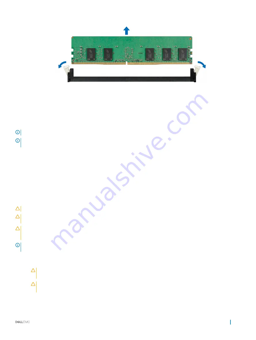
Figure 62. Removing a memory module
Next steps
1
Install the memory module.
2
For configurations with mid drive tray, if you are removing the memory module permanently, install a memory module blank. The
procedure to install a memory module blank is similar to that of the memory module.
NOTE:
For single processor systems, install processor/DIMM blank on CPU2 socket.
NOTE:
To ensure proper cooling, DIMM blank must be installed for systems with mid drive tray
configuration.
Related link
Removing the air shroud
Installing a memory module
Installing a memory module
The procedure for installing a memory module and NVDIMM-N is identical.
Prerequisites
Follow the safety guidelines listed in
CAUTION:
Ensure that you install the NVDIMM-N battery if you are using NVDIMM-N.
CAUTION:
To prevent data loss and potential damage to your system, ensure that your system, LEDs on system, LEDs on
NVDIMM-N and LEDs on NVDIMM-N battery are turned off before installing the NVDIMM-N battery.
CAUTION:
To ensure proper system cooling in configurations with mid drive tray, memory module blanks must be installed in any
memory socket that is not occupied. Remove memory module blanks only if you intend to install memory modules in those
sockets.
NOTE:
You must follow the thermal restriction while using DIMM blank. For information about thermal restriction, see the
Thermal restrictions section.
Steps
1
Locate the appropriate memory module socket.
CAUTION:
Handle each memory module only by the card edges, ensuring not to touch the middle of the memory
module or metallic contacts.
CAUTION:
To prevent damage to the memory module or the memory module socket during installation, do not bend or
flex the memory module. You must insert both ends of the memory module simultaneously.
2
Open the ejectors on the memory module socket outward to allow the memory module to be inserted into the socket.
3
Align the edge connector of the memory module with the alignment key of the memory module socket, and insert the memory module
in the socket.
Installing and removing system components
115
Содержание PowerEdge R740xd
Страница 9: ...Figure 1 Supported configurations PowerEdge R740xd system overview 9 ...
Страница 151: ...Figure 103 Installing GPU 2 and 3 Installing and removing system components 151 ...
Страница 208: ...Related link Removing the system cover Installing the system cover 208 Jumpers and connectors ...


