


Using the System Setup Program
95
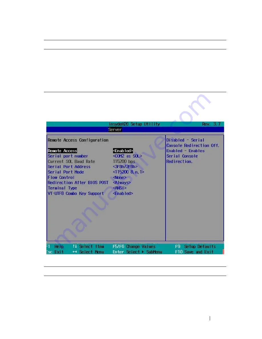
Remote Access Configuration
Scroll to this item and press <Enter> to view the following screen.
Remote Access Configuration
IPv6 Prefix Length
Sets prefix length of the IPv6 address.
IPv6 IP Address
Set the BMC management port to dedicated or shared
NIC port. Options are [Dedicated NIC] and [Shared NIC].
IPv6 IP Address
Sets the BMC IPv6 address.
IPv6 Gateway Address
Sets the MAC address for the static IPv6 address.
Option
Description
Remote Access
(
Enabled
default)
Enables or disables serial console redirection.
Option
Description
Содержание PowerEdge C8220
Страница 1: ...Dell PowerEdge C8220 Hardware Owner s Manual Regulatory Model B05B Regulatory Type B05B001 ...
Страница 138: ...138 Using the System Setup Program ...
Страница 208: ...208 Installing System Components ...
Страница 224: ...224 Troubleshooting ...
Страница 236: ...236 Jumpers and Connectors Expansion Card Riser Connector Figure 5 7 Expansion Card Riser Connector 1 PCIe x16 slot 5 1 ...
Страница 242: ...242 Getting Help ...


