7-2
Dell OptiPlex Gn and Gn+ Low-Profile Systems Reference and Installation Guide
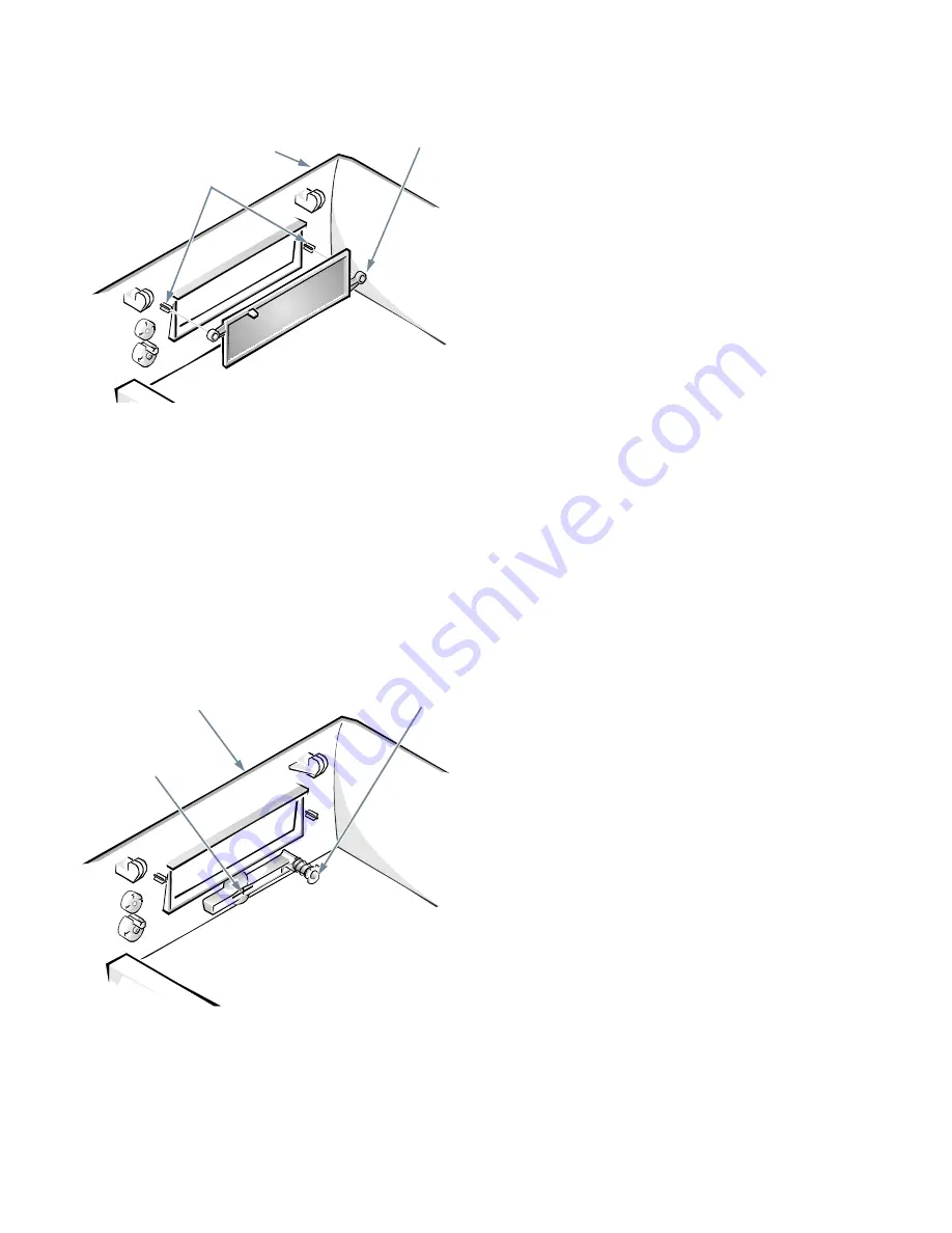
Figure 7-2. Removing the Front-Panel Insert
for the 5.25-Inch Bay
To remove the insert covering the 3.5-inch bay, follow
these steps:
1.
Complete steps 1 through 3 of the procedure for
removing the 5.25-inch insert.
2.
Inside the cover, locate the eject button mecha-
nism for the 3.5-inch bay (see Figure 7-3). Press
the mechanism toward the front panel to snap the
plastic insert out of its opening.
Figure 7-3. Removing the Front-Panel Insert
for the 3.5-Inch Bay
To replace the front-panel insert for the 5.25-inch bay,
work from inside the cover. Position the insert behind the
bay opening, insert the two ring-tabs (see Figure 6-2)
over the posts on the inside of the opening, and firmly
press both ends of the insert into place.
To replace the front-panel insert for the 3.5-inch bay,
work from outside the cover. Place the insert in position
and press it into the opening.
E
IDE Drive Addressing
All EIDE devices should be configured for the Cable
Select jumper position, which assigns master and slave sta-
tus to devices by their position on the interface cable.
When two EIDE devices are connected to a single EIDE
interface cable and are configured for the Cable Select
jumper position, the device attached to the last connector
on the interface cable is the master or boot device (drive 0)
and the device attached to the middle connector on the
interface cable is the slave device (drive 1). Refer to the
drive documentation in your upgrade kit for information
on setting devices to the Cable Select jumper position.
NOTE: If you want to install a second EIDE drive that is
a different type from the first drive but you do not have
the specifications for the first drive, do one of the
following:
•
If you purchased the drive from Dell, you can contact
Dell for the necessary reconfiguration information.
(See the chapter titled “Getting Help” in the Diag-
nostics and Troubleshooting Guide for instructions
on obtaining technical assistance.)
•
If you did not purchase the drive from Dell, call the
drive manufacturer.
With the two EIDE interface connectors on the system
board, your system can support up to four EIDE devices.
EIDE hard-disk drives should be connected to the EIDE
interface connector labeled “IDE1.” (EIDE tape drives
and CD-ROM drives should be connected to the EIDE
interface connector labeled “IDE2.”)
computer cover
(upside down)
ring-tabs (2)
posts
3.5-inch front-
panel insert
computer cover
(upside down)
eject button
mechanism
Содержание OptiPlex Gn+
Страница 1: ... 5 5 1 1 167 7 21 8 HOO 2SWL3OH Q DQG Q RZ 3URILOH 6 VWHPV LWK QKDQFHG 0DQDJHDELOLW 0 ...
Страница 6: ...viii ...
Страница 10: ...xii ...
Страница 18: ...xx ...
Страница 26: ...1 8 Dell OptiPlex Gn and Gn Low Profile Systems Reference and Installation Guide ...
Страница 78: ...6 12 Dell OptiPlex Gn and Gn Low Profile Systems Reference and Installation Guide ...
Страница 88: ...7 10 Dell OptiPlex Gn and Gn Low Profile Systems Reference and Installation Guide ...
Страница 94: ...A 6 Dell OptiPlex Gn and Gn Low Profile Systems Reference and Installation Guide ...
Страница 112: ...D 4 Dell OptiPlex Gn and Gn Low Profile Systems Reference and Installation Guide ...
Страница 121: ......
Страница 122: ... Printed in the U S A www dell com P N 88700 ...
Страница 123: ......
Страница 124: ... Printed in Ireland www dell com P N 88700 ...
Страница 125: ......
Страница 126: ... Printed in Malaysia www dell com P N 88700 ...


