6-8
Dell OptiPlex Gn and Gn+ Low-Profile Systems Reference and Installation Guide
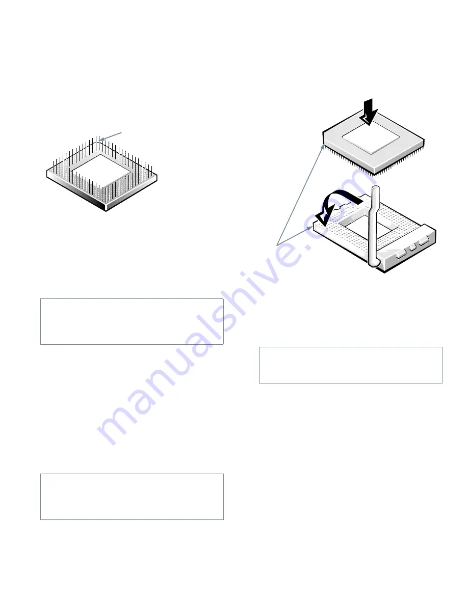
Identify the pin-1 corner of the microprocessor by
turning the chip over and locating the tiny gold fin-
ger that extends from one corner of the large central
rectangular area. The gold finger points toward
pin 1, which is also uniquely identified by a square
pad.
Figure 6-11. Pin-1 Identification
The pin-1 corner of the socket is the bottom-left cor-
ner of the socket (see Figure 6-1).
7.
Install the microprocessor chip in the socket (see
Figure 6-12).
If the release lever on the microprocessor socket is
not all the way out, move it to that position now.
With the pin-1 corners of the chip and socket
aligned, align the pins on the chip with the holes in
the socket. Set the chip lightly in the socket and
make sure all pins are headed into the correct holes.
Because your system uses a ZIF microprocessor
socket, there is no need to use force (which could
bend the pins if the chip is misaligned). When the
chip is positioned correctly, it should seat itself in the
socket with minimal pressure.
When the chip is fully seated in the socket, pivot the
microprocessor-socket release lever back toward the
socket until it snaps into place, securing the chip.
Figure 6-12. Installing the Microprocessor
Chip
8.
Unpack the heat sink included in your upgrade
kit.
Peel the release liner from the adhesive tape that is
attached to the bottom of the heat sink.
9.
Place the heat sink on top of the microprocessor
chip (see Figure 6-13).
CAUTION: Positioning the microprocessor
chip incorrectly in the socket can permanently
damage the chip and the computer when you
turn on the system.
CAUTION: When placing the microprocessor
chip in the socket, be sure that all of the pins go
into the corresponding holes on all sides of the
socket. Be careful not to bend the pins.
pin-1 corner (gold finger
and square pad)
CAUTION: Ground yourself by touching an
unpainted metal surface on the back of the
computer.
pin-1 corners of
chip and socket
aligned
Содержание OptiPlex Gn+
Страница 1: ... 5 5 1 1 167 7 21 8 HOO 2SWL3OH Q DQG Q RZ 3URILOH 6 VWHPV LWK QKDQFHG 0DQDJHDELOLW 0 ...
Страница 6: ...viii ...
Страница 10: ...xii ...
Страница 18: ...xx ...
Страница 26: ...1 8 Dell OptiPlex Gn and Gn Low Profile Systems Reference and Installation Guide ...
Страница 78: ...6 12 Dell OptiPlex Gn and Gn Low Profile Systems Reference and Installation Guide ...
Страница 88: ...7 10 Dell OptiPlex Gn and Gn Low Profile Systems Reference and Installation Guide ...
Страница 94: ...A 6 Dell OptiPlex Gn and Gn Low Profile Systems Reference and Installation Guide ...
Страница 112: ...D 4 Dell OptiPlex Gn and Gn Low Profile Systems Reference and Installation Guide ...
Страница 121: ......
Страница 122: ... Printed in the U S A www dell com P N 88700 ...
Страница 123: ......
Страница 124: ... Printed in Ireland www dell com P N 88700 ...
Страница 125: ......
Страница 126: ... Printed in Malaysia www dell com P N 88700 ...


