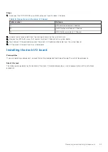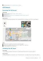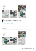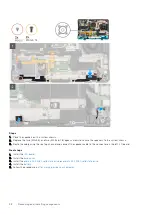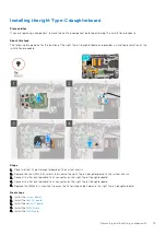
Steps
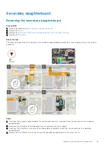
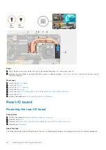
1. Peel the adhesive tape and unroute the cables from the routing channels on the system chassis.
2. Disconnect the rear I/O flat printed cable and remove the two (M2.5x5) screws that secure the rear I/O board to the
system board.
NOTE:
Disconnect the GPS cable and tilt the rear I/O board at an angle to remove it.
Installing the rear I/O board
Prerequisites
If you are replacing a component, remove the existing component before performing the installation procedure.
About this task
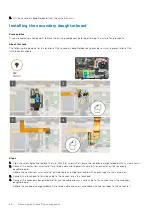
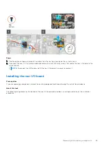
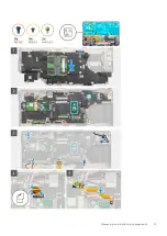
The following image indicates the location of the rear I/O board and provides a visual representation of the installation
procedure.
Removing and installing components
65
Содержание Latitude 5430
Страница 1: ...Latitude 5430 Rugged Service Manual Regulatory Model P148G Regulatory Type P148G001 May 2022 Rev A01 ...
Страница 19: ...Removing and installing components 19 ...
Страница 21: ...Removing and installing components 21 ...
Страница 25: ...Removing and installing components 25 ...
Страница 31: ...Removing and installing components 31 ...
Страница 34: ...34 Removing and installing components ...
Страница 69: ...Removing and installing components 69 ...
Страница 73: ...Removing and installing components 73 ...
Страница 90: ...90 Removing and installing components ...
Страница 95: ...Removing and installing components 95 ...
Страница 138: ...138 Troubleshooting ...

