background image

Riser 

configuration


and supported 

risers

Slot description PCIe slots on 

riser 1 (Height 

and length)

Processor 

connection

PCIe slots on riser 

2 (Height and 

length)

Processor 

connection

PCIe slots on 

riser 3 (Height 

and length)

Processor 

connection

Riser 
configuration 6 
(1D+2A+3A)

Five x8 and 
three x16 slots

Slot1: x16 full-
height, full length

Processor 1 Slot 4: x16 full-

height, full length

Processor 2 Slot 7: x8 full-

height, full length

Processor 
2

Slot 2: x8 full-
height, full length

Processor 1 Slot 5: x8 full-

height, full length

Processor 2 Slot 8: x16 full-

height, full length

Processor 
2

Slot 3: x8 full-
height, half length

Processor 1 Slot 6: x8 low 

profile, half length

Processor 1

Table 43. Riser configurations with 4 PCIe slots [Riser configuration 1 (1B+2B) and Riser configuration 2 (1B+2C)]

Card Type

Slot priority

Maximum number of cards

GPU (double width)

N/A

N/A

GPU (single width)

N/A

N/A

PCIe Bridge

4

1

Internal storage adapter

4

1

Express Flash NVMe PCIe SSD adapter

1, 2, 3, 4

4

HCA EDR

4

1

100 GB NIC

4

1

100 G OPA

4

1

HCA FDR

4

1

40 GB NIC

1, 2, 3

3

40 GB NIC

4

1

HBA FC32

1, 2, 3

3

HBA FC32

4

1

25 GB NIC

1, 2, 3

3

25 GB NIC

4

1

HBA FC16

1, 2, 3

3

HBA FC16

4

1

10 GB NIC

1, 2, 3

3

10 GB NIC

4

1

HBA FC8

1, 2, 3

3

HBA FC8

4

1

1 GB NIC

1, 2, 3

3

1 GB NIC

4

1

External storage adapter

1, 2, 3

3

External storage adapter

4

1

BOSS

1, 2, 3

1

104

Dell EMC PowerEdge R740 Installation and Service Manual
Installing and removing system components

Содержание EMC PowerEdge R740

Страница 1: ...Dell EMC PowerEdge R740 Installation and Service Manual Regulatory Model E38S Series Regulatory Type E38S001 ...

Страница 2: ... to hardware or loss of data and tells you how to avoid the problem WARNING A WARNING indicates a potential for property damage personal injury or death Copyright 2017 Dell Inc or its subsidiaries All rights reserved Dell EMC and other trademarks are trademarks of Dell Inc or its subsidiaries Other trademarks may be trademarks of their respective owners 2017 07 Rev A00 ...

Страница 3: ...ht 27 Processor specifications 28 PSU specifications 28 System battery specifications 28 Expansion bus specifications 28 Memory specifications 30 Storage controller specifications 30 Drive specifications 30 Hard drives 30 Optical drive 31 Ports and connectors specifications 31 USB ports 31 NIC ports 31 VGA ports 31 Serial connector 31 Internal Dual SD Module vFlash card 32 Video specifications 32 ...

Страница 4: ...ot Manager main menu 64 One shot BIOS boot menu 64 System Utilities 64 PXE boot 64 6 Installing and removing system components 65 Safety instructions 65 Before working inside your system 65 After working inside your system 65 Recommended tools 66 Front bezel optional 66 Removing the optional front bezel 66 Installing the optional front bezel 67 System cover 68 Removing the system cover 68 Installi...

Страница 5: ...rocessor and heat sink module 96 Removing the processor from the processor and heat sink module 97 Installing the processor into a processor and heat sink module 99 Installing a processor and heat sink module 101 Expansion cards and expansion card risers 102 Expansion card installation guidelines 103 Opening and closing the PCIe card holder latch 106 Removing the expansion card from expansion card...

Страница 6: ...145 Internal USB memory key optional 146 Replacing optional internal USB memory key 146 Optical drive optional 146 Removing the optional optical drive 146 Installing the optional optical drive 147 Power supply units 148 Hot spare feature 149 Removing a power supply unit blank 149 Installing a power supply unit blank 150 Removing a power supply unit 150 Installing a power supply unit 151 Wiring ins...

Страница 7: ...m diagnostic controls 165 8 Jumpers and connectors 166 System board jumpers and connectors 167 System board jumper settings 169 Disabling forgotten password 169 9 Getting help 171 Contacting Dell 171 Documentation feedback 171 Accessing system information by using QRL 171 Quick Resource Locator for PowerEdge R740 and R740xd systems 172 Receiving automated support with SupportAssist 172 Dell EMC Po...

Страница 8: ... SSDs For more information about supported drives see the Technical specifications section Topics Supported configurations Front view of the system Back view of the system Hard drive indicator codes LCD panel Locating Service Tag of your system Related links Technical specifications Supported configurations The PowerEdge R740 system supports the following configurations 1 8 Dell EMC PowerEdge R740...

Страница 9: ...Figure 1 Supported configurations Dell EMC PowerEdge R740 Installation and Service Manual PowerEdge R740 system overview 9 ...

Страница 10: ...the front of the system Figure 2 Front view of 16 x 2 5 inch hard drive system Figure 3 Front view of 8 x 2 5 inch hard drive system Figure 4 Front view of 8 x 3 5 inch hard drive system 10 Dell EMC PowerEdge R740 Installation and Service Manual PowerEdge R740 system overview ...

Страница 11: ...rmation see the Technical specifications section 4 USB 3 0 port optional The USB ports are 9 pin 3 0 compliant These ports enable you to connect USB devices to the system 5 Right control panel N A Contains the power button VGA port iDRAC Direct micro USB port and two USB 2 0 ports 6 Information tag N A The Information Tag is a slide out label panel that contains system information such as Service ...

Страница 12: ...s LED indicators are always off and only turns on to a solid amber if any error occurs Table 3 Status LED indicators and descriptions Icon Description Condition Corrective action Drive indicator The indicator turns solid amber if there is a drive error Check the System Event Log to determine if the drive has an error Run the appropriate Online Diagnostics test Restart the system and run embedded d...

Страница 13: ...e left control panel of your system Figure 6 System health and system ID indicators Table 4 System health and system ID indicator codes System health and system ID indicator code Condition Solid blue Indicates that the system is turned on system is healthy and system ID mode is not active Press the system health and system ID button to switch to system ID mode Blinking blue Indicates that the syst...

Страница 14: ...the indicator continues to blink indefinitely see the Getting help section Blinks white slowly Indicates that firmware update is in progress If the indicator continues to blink indefinitely see the Getting help section Blinks white five times rapidly and then turns off Indicates that the iDRAC Quick Sync 2 feature is disabled Check if iDRAC Quick Sync 2 feature is configured to be disabled by iDRA...

Страница 15: ...ore information see the iDRAC User s Guide at Dell com idracmanuals 4 iDRAC Direct LED N A The iDRAC Direct LED indicator lights up to indicate that the iDRAC Direct port is connected For more information see the iDRAC Direct LED indicator codes section 5 VGA port Enables you to connect a display device to the system For more information see the Technical specifications section Related links iDRAC...

Страница 16: ...card slot riser 1 connects up to three full height PCIe expansion cards to the system For more information see the Expansion card installation guidelines section 2 Half height PCIe expansion card slot N A The PCIe expansion card slot riser 2 connects one half height PCIe expansion cards to the system For more information see the Expansion card installation guidelines section 3 Rear handle N A The ...

Страница 17: ...ems Press the button to identify a system in a rack by turning on the system ID button You can also use the system ID button to reset iDRAC and to access BIOS using the step through mode Related links Expansion card installation guidelines Technical specifications NIC indicator codes Each NIC on the back panel has indicators that provide information about the activity and link status The activity ...

Страница 18: ... not connected to the PSU Blinking green When the firmware of the PSU is being updated the PSU handle blinks green CAUTION Do not disconnect the power cord or unplug the PSU when updating firmware If firmware update is interrupted the PSUs do not function Blinking green and turns off When hot plugging a PSU the PSU handle blinks green five times at a rate of 4 Hz and turns off This indicates a PSU...

Страница 19: ...een This indicates that there is a PSU mismatch with respect to efficiency feature set health status or supported voltage CAUTION If two PSUs are installed both the PSUs must have the same type of label for example Extended Power Performance EPP label Mixing PSUs from previous generations of PowerEdge servers is not supported even if the PSUs have the same power rating This results in a PSU mismat...

Страница 20: ...s LED indicator does not turn on Table 12 Hard drive indicator codes Hard drive status indicator code Condition Flashes green twice per second Identifying drive or preparing for removal Off Drive ready for removal NOTE The drive status indicator remains off until all drives are initialized after the system is turned on Drives are not ready for removal during this time Flashes green amber and then ...

Страница 21: ...system turns off and there are no errors LCD enters the standby mode after five minutes of inactivity Press any button on the LCD to turn it on If the LCD panel stops responding remove the bezel and reinstall it If the problem persists see the Getting help section The LCD backlight remains off if LCD messaging is turned off using the iDRAC utility the LCD panel or other tools Figure 14 LCD panel f...

Страница 22: ... to view domain addresses Two separate DNS entries are available Set error Select SEL to view LCD error messages in a format that matches the IPMI description in the SEL This enables you to match an LCD message with an SEL entry Select Simple to view LCD error messages in a simplified user friendly description For more information about error messages see the Dell Event and Error Messages Referenc...

Страница 23: ...ice Tag Pull out the information tag in front of the system to view the Express Service Code and Service Tag Alternatively the information may be on a sticker on the chassis of the system The mini Enterprise Service Tag EST is found on the back of the system This information is used by Dell to route support calls to the appropriate personnel Figure 15 Locating Service Tag of your system 1 informat...

Страница 24: ...ACADM subcommands and supported RACADM interfaces see the RACADM Command Line Reference Guide for iDRAC Dell com idracmanuals For information about updating drivers and firmware see the Methods to download firmware and drivers section in this document To download drivers Dell com support drivers Managing your system For information about systems management software offered by Dell see the Dell Ope...

Страница 25: ...the Storage controller documentation Dell com storagecontrollermanuals Understanding event and error messages For information about checking the event and error messages generated by the system firmware and agents that monitor system components see the Dell Event and Error Messages Reference Guide Dell com openmanagemanuals OpenManage software Troubleshooting your system For information about iden...

Страница 26: ...cations System battery specifications Expansion bus specifications Memory specifications Storage controller specifications Drive specifications Ports and connectors specifications Video specifications Environmental specifications System dimensions This section describes the physical dimensions of the system 3 26 Dell EMC PowerEdge R740 Installation and Service Manual Technical specifications ...

Страница 27: ...09 inches 86 8 mm 3 42 inches 35 84 mm 1 41 inches 22 0 mm 0 87 inches 678 8 mm 26 72 inches 715 5 mm 28 17 inches Chassis weight Table 16 Chassis weight System Maximum weight with all hard drives SSDs 2 5 inch hard drive systems 26 3 kg 57 98 lb 3 5 inch hard drive systems 28 6 kg 63 05 lb Dell EMC PowerEdge R740 Installation and Service Manual Technical specifications 27 ...

Страница 28: ...tinum 6000 BTU hr 50 60 Hz 100 240 V AC autoranging 10 A 2000 W AC Platinum 7500 BTU hr 50 60 Hz 100 240 V AC autoranging 11 5 A NOTE Heat dissipation is calculated using the PSU wattage rating NOTE This system is also designed to connect to the IT power systems with a phase to phase voltage not exceeding 240 V NOTE If a system with 2000 W AC PSU operates at low line 100 120 V AC then the power ra...

Страница 29: ...th Processor 1 Riser configuration 4 1A 2A 3A Three x8 and four x16 slots Slot 1 x16 full height full length Processor 1 Slot 4 x16 full height full length Processor 2 Slot 7 x8 full height full length Processor 2 N A N A Slot 5 x8 full height full length Processor 2 Slot 8 x16 full height full length Processor 2 Slot 3 x16 full height half length Processor 1 Slot 6 x8 low profile half length Proc...

Страница 30: ...e required for any configurations that support NVDIMM N Storage controller specifications The PowerEdge R740 system supports Internal storage controller cards PowerEdge RAID Controller PERC H330 PERC H730P PERC H740P HBA330 S140 and Boot Optimized Server Storage BOSS S1 External storage controller cards PERC H840 and 12Gbps SAS HBA Drive specifications Hard drives The PowerEdge R740 system support...

Страница 31: ...gurations Four RJ 45 ports that support 10 100 and 1000 Mbps Four RJ 45 ports that support 100 M 1 G and 10 Gbps Four RJ 45 ports where two ports support maximum of 10 G and the other two ports maximum of 1 G Two RJ 45 ports that support up to 1 Gbps and 2 SFP ports that support up to 10 Gbps Four SFP ports that support up to 10 Gbps Two SFP28 ports that support up to 25 Gbps NOTE You can install ...

Страница 32: ... frame buffer Table 21 Supported video resolution options Resolution Refresh rate Hz Color depth bits 1024 x 768 60 8 16 32 1280 x 800 60 8 16 32 1280 x 1024 60 8 16 32 1360 x 768 60 8 16 32 1440 x 900 60 8 16 32 1600 x 900 60 8 16 32 1600 x 1200 60 8 16 32 1680 x 1050 60 8 16 32 1920 x 1080 60 8 16 32 1920 x 1200 60 8 16 32 NOTE 1920 x 1080 and 1920 x 1200 resolutions are only supported in reduce...

Страница 33: ...ock pulses in the positive and negative x y and z axes of 6 G for up to 11 ms Storage Six consecutively executed shock pulses in the positive and negative x y and z axes one pulse on each side of the system of 71 G for up to 2 ms Table 26 Maximum altitude specifications Maximum altitude Specifications Operating 3048 m 10 000 ft Storage 12 000 m 39 370 ft Table 27 Operating temperature de rating sp...

Страница 34: ...re 10 C to 35 C the system can operate down to 5 C or up to 45 C for a maximum of 1 of its annual operating hours For temperatures between 40 C and 45 C de rate maximum allowable temperature by 1 C per 125 m above 950 m 1 F per 228 ft NOTE When operating in the expanded temperature range system performance may be impacted NOTE When operating in the expanded temperature range ambient temperature wa...

Страница 35: ...ay impact system performance Table 31 Configuration based ambient temperature restrictions System Front backplane CPU Thermal Design Power TDP CPU heat sink Fan type GPU Ambient restriction PowerEdge R740 8 x 3 5 inch SAS SATA 150 W 8 core 165 W 12 core 200 W 205 W 1U high performance High performance fan 1 double width single width 30 C 8 x 2 5 inch SAS SATA 150 W 8 core 165 W 12 core 200 W 205 W...

Страница 36: ...ive dust zinc whiskers or other conductive particles NOTE This condition applies to data center and non data center environments Corrosive dust Air must be free of corrosive dust Residual dust present in the air must have a deliquescent point less than 60 relative humidity NOTE This condition applies to data center and non data center environments Table 33 Gaseous contamination specifications Gase...

Страница 37: ...f Dell systems iDRAC alerts administrators to system issues helps them perform remote system management and reduces the need for physical access to the system Options to set up iDRAC IP address You must configure the initial network settings based on your network infrastructure to enable the communication to and from iDRAC You must use the default iDRAC IP address 192 168 0 120 to configure the in...

Страница 38: ...ame and password after setting up the iDRAC IP address For more information about logging in to the iDRAC and iDRAC licenses see the latest Integrated Dell Remote Access Controller User s Guide at Dell com idracmanuals You can also access iDRAC by using RACADM For more information see the RACADM Command Line Interface Reference Guide at Dell com idracmanuals Options to install the operating system...

Страница 39: ...Dell recommends that you download and install the latest BIOS drivers and systems management firmware on your system Prerequisites Ensure that you clear the web browser cache before downloading the drivers and firmware Steps 1 Go to Dell com support drivers 2 In the Drivers Downloads section type the Service Tag of your system in the Enter a Service Tag or product ID box and then click Submit NOTE...

Страница 40: ...tion Environment PXE Related links System Setup Dell Lifecycle Controller Boot Manager PXE boot System Setup By using the System Setup screen you can configure the BIOS settings iDRAC settings and device settings of your system NOTE Help text for the selected field is displayed in the graphical browser by default To view the help text in the text browser press F1 You can access system setup by usi...

Страница 41: ...IOS Enables you to configure BIOS settings iDRAC Settings Enables you to configure the iDRAC settings The iDRAC settings utility is an interface to set up and configure the iDRAC parameters by using UEFI Unified Extensible Firmware Interface You can enable or disable various iDRAC parameters by using the iDRAC settings utility For more information about this utility see Integrated Dell Remote Acce...

Страница 42: ... System BIOS Settings details The System BIOS Settings screen details are explained as follows Option Description System Information Specifies information about the system such as the system model name BIOS version and Service Tag Memory Settings Specifies information and options related to the installed memory Processor Settings Specifies information and options related to the processor such as s...

Страница 43: ...tem Information You can use the System Information screen to view system properties such as Service Tag system model name and the BIOS version Viewing System Information To view the System Information screen perform the following steps 1 Turn on or restart your system 2 Press F2 immediately after you see the following message F2 System Setup NOTE If your operating system begins to load before you ...

Страница 44: ... booting and then restart your system and try again 3 On the System Setup Main Menu screen click System BIOS 4 On the System BIOS screen click Memory Settings Memory Settings details The Memory Settings screen details are explained as follows Option Description System Memory Size Specifies the memory size in the system System Memory Type Specifies the type of memory installed in the system System ...

Страница 45: ...olatile DIMM persistency for all NVDIMM N is enabled and presented to OS data is preserved This option is set to Non Volatile DIMM by default NVDIMM N Read Only Enables or disables the read only option for the NVDIMM N If set to Enable all NVDIMM N is forced to read only Read only is intended to be for debug or maintenance when customers would like to access the NVDIMM N data and also to lock it f...

Страница 46: ... follows Option Description Logical Processor Enables or disables the logical processors and displays the number of logical processors If this option is set to Enabled the BIOS displays all the logical processors If this option is set to Disabled the BIOS displays only one logical processor per core This option is set to Enabled by default CPU Interconnect Speed Enables you to govern the frequency...

Страница 47: ...arks some of the logical processors in the system which in turn allows the corresponding processor cores to transition into a lower power idle state This option can only be enabled if the operating system supports it It is set to Disabled by default X2APIC Mode Enables or disables the X2APIC mode This option is set to Disabled by default Dell Controlled Turbo Controls the turbo engagement Enable t...

Страница 48: ...ort n Sets the drive type of the selected device For AHCI or RAID mode BIOS support is always enabled Option Description Model Specifies the drive model of the selected device Drive Type Specifies the type of drive attached to the SATA port Capacity Specifies the total capacity of the hard drive This field is undefined for removable media devices such as optical drives Boot Settings You can use th...

Страница 49: ...nabled and the system fails to boot the system re attempts the boot sequence after 30 seconds This option is set to Enabled by default Hard Disk Failover Specifies the hard drive that is booted in the event of a hard drive failure The devices are selected in the Hard Disk Drive Sequence on the Boot Option Setting menu When this option is set to Disabled only the first hard drive in the list is att...

Страница 50: ...the plus and minus sign keys to move the device down or up in the order 3 Click Exit and then click Yes to save the settings on exit Network Settings You can use the Network Settings screen to modify UEFI PXE iSCSI and HTTP boot settings The network settings option is available only in the UEFI mode NOTE The BIOS does not control network settings in the BIOS mode For the BIOS boot mode the option ...

Страница 51: ... 1 Turn on or restart your system 2 Press F2 immediately after you see the following message F2 System Setup NOTE If your operating system begins to load before you press F2 wait for the system to finish booting and then restart your system and try again 3 On the System Setup Main Menu screen click System BIOS 4 On the System BIOS screen click Network Settings 5 On the Network Settings screen clic...

Страница 52: ...his option is set to Enabled by default Integrated RAID Controller Enables or disables the integrated RAID controller This option is set to Enabled by default Integrated Network Card 1 Enables or disables the integrated network card NDC When set to Disabled the NDC is not available to the operating system OS This option is set to Enable by default NOTE If set to Disabled OS the Integrated NICs mig...

Страница 53: ...ect on the system Memory Mapped I O above 4 GB Enables or disables the support for the PCIe devices that need large amounts of memory Enable this option only for 64 bit operating systems This option is set to Enabled by default Memory Mapped I O above Base When set to 12 TB the system will map MMIO base to 12 TB Enable this option for an OS that requires 44 bit PCIe addressing When set to 512 GB t...

Страница 54: ...nication Serial Communication details The Serial Communication screen details are explained as follows Option Description Serial Communication Selects serial communication devices Serial Device 1 and Serial Device 2 in BIOS BIOS console redirection can also be enabled and the port address can be specified This option is set to Auto by default Serial Port Address Enables you to set the port address...

Страница 55: ...erformance settings such as power management Viewing System Profile Settings To view the System Profile Settings screen perform the following steps 1 Turn on or restart your system 2 Press F2 immediately after you see the following message F2 System Setup NOTE If your operating system begins to load before you press F2 wait for the system to finish booting and then restart your system and try agai...

Страница 56: ... to select the Energy Efficient Policy option The CPU uses the setting to manipulate the internal behavior of the processor and determines whether to target higher performance or better power savings Number of Turbo Boot Enabled Cores for Processor 1 NOTE If there are two processors installed in the system you will see an entry for Number of Turbo Boost Enabled Cores for Processor 2 Controls the n...

Страница 57: ...setting needs to be set to Enabled to avoid updating errors Intel AES NI Improves the speed of applications by performing encryption and decryption by using the Advanced Encryption Standard Instruction Set AES NI This option is set to Enabled by default System Password Sets the system password This option is set to Enabled by default and is read only if the password jumper is not installed in the ...

Страница 58: ... of securing UEFI variables When set to Standard the default UEFI variables are accessible in the operating system per the UEFI specification When set to Controlled selected UEFI variables are protected in the environment and new UEFI boot entries are forced to be at the end of the current boot order Secure Boot Enables Secure Boot where the BIOS authenticates each pre boot image by using the cert...

Страница 59: ...s 1 To enter System Setup press F2 immediately after turning on or rebooting your system 2 On the System Setup Main Menu screen click System BIOS System Security 3 On the System Security screen verify that Password Status is set to Unlocked 4 In the System Password field type your system password and press Enter or Tab A message prompts you to reenter the system password 5 Reenter the system passw...

Страница 60: ...en press Enter or Tab If you change the system and setup password a message prompts you to reenter the new password If you delete the system and setup password a message prompts you to confirm the deletion 6 Press Esc to return to the System BIOS screen Press Esc again and a message prompts you to save the changes Operating with setup password enabled If Setup Password is set to Enabled type the c...

Страница 61: ...ng devices None IDSDM SATA Ports in AHCI mode BOSS PCIe Cards Internal M 2 Drives Internal USB NOTE RAID configurations and NVMe cards not are included as BIOS does not have the ability to distinguish between individual drives in those configurations Redundant OS State NOTE This option is disabled if Redundant OS Location is set to None When set to Visible the backup disk is visible to the boot li...

Страница 62: ...not apply to 84 key keyboards F1 F2 Prompt on Error Enables or disables the F1 F2 prompt on error This option is set to Enabled by default The F1 F2 prompt also includes keyboard errors Load Legacy Video Option ROM Enables you to determine whether the system BIOS loads the legacy video INT 10H option ROM from the video controller Selecting Enabled in the operating system does not support UEFI vide...

Страница 63: ...sequence and can function independently of the operating system NOTE Certain platform configurations may not support the full set of features provided by the Dell Lifecycle Controller For more information about setting up the Dell Lifecycle Controller configuring hardware and firmware and deploying the operating system see the Dell Lifecycle Controller documentation at Dell com idracmanuals Relate...

Страница 64: ...invokes the Dell Lifecycle Controller program System Utilities Enables you to launch System Utilities menu such as System Diagnostics and UEFI shell Related links Boot Manager Viewing Boot Manager One shot BIOS boot menu One shot BIOS boot menu enables you to select a boot device to boot from Related links Boot Manager System Utilities System Utilities contains the following utilities that can be ...

Страница 65: ...tistatic strap while working on components inside the system CAUTION To ensure proper operation and cooling all bays in the system and system fans must be always populated with a component or a blank Before working inside your system Prerequisites Follow the safety guidelines listed in Safety instructions Steps 1 Turn off the system including any attached peripherals 2 Disconnect the system from t...

Страница 66: ...ay system branding A lock on the bezel is used to protect unauthorized access to the hard drives There are two versions of bezel available With LCD panel Without LCD panel For bezels with LCD panel the system status can be viewed on the LCD panel For more information see the LCD panel section The LCD bezel is hot pluggable and can be used in any server of the same branding even if that system was ...

Страница 67: ...panel is the same Prerequisites Follow the safety guidelines listed in Safety instructions Steps 1 Locate and remove the bezel key NOTE The bezel key is part of the LCD bezel package 2 Align and insert the right end of the bezel onto the system 3 Press the release button and fit the left end of the bezel onto the system 4 Lock the bezel by using the key Dell EMC PowerEdge R740 Installation and Ser...

Страница 68: ...ny attached peripherals 3 Disconnect the system from the electrical outlet and disconnect the peripherals Steps 1 Using a flat or a Phillips head screwdriver rotate the latch release lock counter clockwise to the unlocked position 2 Lift the latch till the system cover slides back and the tabs on the system cover disengage from the guide slots on the system 3 Hold the cover on both sides and lift ...

Страница 69: ...teps 1 Align the tabs on the system cover with the guide slots on the system 2 Push the system cover latch down The system cover slides forward the tabs on the system cover engage with the guide slots on the system and the system cover latch locks into place 3 Using a flat or Phillips head screwdriver rotate the latch release lock clockwise to the locked position Dell EMC PowerEdge R740 Installati...

Страница 70: ...he backplane cover Prerequisites 1 Follow the safety guidelines listed in Safety instructions 2 Follow the procedure listed in Before working inside your system Steps 1 Slide the backplane cover in the direction of the arrows marked on the backplane cover 2 Lift the backplane cover away from the system 70 Dell EMC PowerEdge R740 Installation and Service Manual Installing and removing system compon...

Страница 71: ...es Follow the safety guidelines listed in Safety instructions Steps 1 Align the backplane cover with the guide slots on the system 2 Slide the backplane cover toward the front of the system until the cover locks into place Dell EMC PowerEdge R740 Installation and Service Manual Installing and removing system components 71 ...
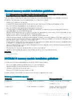
Страница 72: ...nly perform troubleshooting and simple repairs as authorized in your product documentation or as directed by the online or telephone service and support team Damage due to servicing that is not authorized by Dell is not covered by your warranty Read and follow the safety instructions that are shipped with your product 72 Dell EMC PowerEdge R740 Installation and Service Manual Installing and removi...

Страница 73: ...processor and heat sink module socket with dust cover 6 expansion card riser 3 7 network daughter card 8 expansion card riser 2 9 system board 10 expansion card riser 1 11 integrated storage controller card 12 CPU1 processor and heat sink module Dell EMC PowerEdge R740 Installation and Service Manual Installing and removing system components 73 ...

Страница 74: ...6 network daughter card 7 expansion card riser 2 8 system board 9 expansion card riser 1 10 integrated storage controller card 11 NVDIMM N battery Air shroud The air shroud directs the airflow across the entire system Air shroud prevents the system from overheating and is used to maintain uniform airflow inside the system 74 Dell EMC PowerEdge R740 Installation and Service Manual Installing and re...

Страница 75: ...M N battery is not hot swappable To prevent data loss and potential damage to your system ensure that your system LEDs on system LEDs on NVDIMM N and LEDs on NVDIMM N battery are turned off before disconnecting the NVDIMM N battery cables Steps Hold the air shroud at both ends and lift it away from the system Figure 25 Removing air shroud Next steps If applicable install the air shroud Related lin...

Страница 76: ...nsure that your system LEDs on system LEDs on NVDIMM N and LEDs on NVDIMM N battery are turned off before connecting the NVDIMM N battery cables 4 Follow the procedure listed in After working inside your system Related links Installing expansion card into expansion card riser Installing GPU card Cooling fan assembly The cooling fan assembly ensures that the key components of the server such as the...

Страница 77: ...tions CAUTION Ensure that the cables inside the system are correctly installed and retained by the cable retention bracket before installing the cooling fan assembly Incorrectly installed cables may get damaged Steps 1 Align the guide rails on the cooling fan assembly with the standoffs on the system 2 Lower the cooling fan assembly into the system until the cooling fan connectors engage with the ...

Страница 78: ...Each fan is listed in the systems management software referenced by the respective fan number If there is a problem with a particular fan you can easily identify and replace the proper fan by noting the fan numbers on the cooling fan assembly Removing a cooling fan The procedure for removing standard and high performance fans is identical Prerequisites WARNING Opening or removing the system cover ...

Страница 79: ...ING Opening or removing the system cover when the system is on may expose you to a risk of electric shock Exercise utmost care while removing or installing cooling fans CAUTION The cooling fans are hot swappable To maintain proper cooling while the system is on replace only one fan at a time Follow the safety guidelines listed in Safety instructions Steps 1 Holding the release tab align the connec...

Страница 80: ... creates a log entry in the system event log SEL This switch is activated when the cover of your system is removed Removing an intrusion switch Prerequisites 1 Follow the safety guidelines listed in Safety instructions 2 Follow the procedure listed in Before working inside your system 3 Remove the cooling fan assembly Steps Press the intrusion switch and slide it out of the intrusion switch slot 8...

Страница 81: ...witch Installing an intrusion switch Prerequisites Follow the safety guidelines listed in Safety instructions Steps 1 Align the tabs on the intrusion switch with the slots on the cooling fan assembly 2 Push the intrusion switch until it locks in place Dell EMC PowerEdge R740 Installation and Service Manual Installing and removing system components 81 ...

Страница 82: ...swappable To prevent data loss and potential damage to your system ensure that your system LEDs on system LEDs on NVDIMM N and LEDs on NVDIMM N battery are turned off before removing the NVDIMM N battery CAUTION To avoid damage to the battery connector you must firmly support the connector while installing or removing a battery Steps 1 Disconnect the cables from the NVDIMM N battery 2 Using Philli...

Страница 83: ...r system ensure that your system LEDs on system LEDs on NVDIMM N and LEDs on NVDIMM N battery are turned off before installing the NVDIMM N battery CAUTION To avoid damage to the battery connector you must firmly support the connector while installing or removing a battery Steps 1 Incline the NVDIMM N battery at an angle and place the battery on the air shroud slot 2 Using Phillips 2 screwdriver t...

Страница 84: ...en you format a hard drive allow enough time for the formatting to complete Be aware that high capacity hard drives can take a long time to format Removing a hard drive blank The procedure for removing 2 5 inch and 3 5 inch hard drive blanks is identical Prerequisites 1 Follow the safety guidelines listed in Safety instructions 2 If installed remove the front bezel CAUTION To maintain proper syste...

Страница 85: ...nes listed in Safety instructions CAUTION Mixing hard drive blanks from previous generations of PowerEdge servers is not supported Steps Insert the hard drive blank into the hard drive slot and push until the release button clicks into place Figure 36 Installing a hard drive blank Next steps 1 If removed install the front bezel 2 Follow the procedure listed in After working inside your system Rela...

Страница 86: ...is configured correctly to support hard drive removal and insertion CAUTION Mixing hard drives from previous generations of PowerEdge servers is not supported CAUTION To prevent data loss ensure that your operating system supports drive installation See the documentation supplied with your operating system Steps 1 Press the release button to open the hard drive release handle 2 Holding the handle ...

Страница 87: ...drive installation See the documentation supplied with your operating system CAUTION When a replacement hot swappable hard drive is installed and the system is powered on the hard drive automatically begins to rebuild Ensure that the replacement hard drive is blank or contains data that you wish to overwrite Any data on the replacement hard drive is immediately lost after the hard drive is install...

Страница 88: ...rd drive carrier Installing a hard drive into the hard drive carrier Prerequisites Follow the safety guidelines listed in Safety instructions CAUTION Mixing hard drives from previous generations of PowerEdge servers is not supported Steps 1 Insert the hard drive into the hard drive carrier with the connector end of the hard drive towards the back of the carrier 2 Align the screw holes on the hard ...

Страница 89: ...T s depending on the following factors DIMM type RDIMM or LRDIMM Number of DIMMs populated per channel System profile selected for example Performance Optimized or Custom can be run at high speed or lower Maximum supported DIMM frequency of the processors Your system contains 24 memory sockets split into two sets of 12 sockets one set per processor Each 12 socket set is organized into six channels...

Страница 90: ...l 3 Channel 4 Channel 5 Proces sor 1 Slots A1 and A7 Slots A2 and A8 Slots A3 and A9 Slots A4 and A10 Slots A5 and A11 Slots A6 and A12 Proces sor 2 Slots B1 and B7 Slots B2 and B8 Slots B3 and B9 Slots B4 and B10 Slots B5 and B11 Slots B6 and B12 90 Dell EMC PowerEdge R740 Installation and Service Manual Installing and removing system components ...

Страница 91: ...GB memory modules populate 16 GB memory modules in the sockets with white release tabs and 8 GB memory modules in the sockets with black release tabs In a dual processor configuration the memory configuration for each processor should be identical For example if you populate socket A1 for processor 1 then populate socket B1 for processor 2 and so on Memory modules of different capacities can be mi...

Страница 92: ...nfiguration 8 22x 32 GB RDIMMs 4x NVDIMM Ns RDIMMs Same for all 12x RDIMM configurations See Config 1 NVDIMM N C1 7 8 C2 7 8 Configuration 9 20x 32 GB RDIMMs 4x NVDIMM Ns RDIMMs C1 1 2 3 4 5 6 7 8 9 10 C2 1 2 3 4 5 6 7 8 9 10 NVDIMM N C1 11 12 C2 11 12 Configuration 10 12x 16 GB RDIMMs 6x NVDIMM Ns RDIMMs Same for all 12x RDIMM configurations See Config 1 NVDIMM N C1 7 8 9 C2 7 8 9 Configuration 1...

Страница 93: ...rectable failure Requires population of three ranks or more per channel With single rank memory sparing enabled the system memory available to the operating system is reduced by one rank per channel For example in a dual processor configuration with twenty four 16 GB dual rank memory modules the available system memory is 3 4 ranks channel 24 memory modules 16 GB 288 GB and not 24 memory modules 1...

Страница 94: ... population order C1 1 C2 1 C1 2 C2 2 C1 3 C2 3 C1 4 C2 4 C1 5 C2 5 Populate in this order odd amount per CPU allowed Requires three ranks or more per channel Fault resilient population order C1 1 2 3 4 5 6 C2 1 2 3 4 5 6 C1 7 8 9 10 11 12 C2 7 8 9 10 11 12 Supported with 6 or 12 DIMMs per CPU Removing a memory module The procedure for removing a memory module and NVDIMM N is identical Prerequisit...

Страница 95: ...ges ensuring not to touch the middle of the memory module or metallic contacts CAUTION To prevent damage to the memory module or the memory module socket during installation do not bend or flex the memory module You must insert both ends of the memory module simultaneously 2 Open the ejectors on the memory module socket outward to allow the memory module to be inserted into the socket 3 Align the ...

Страница 96: ...Settings Processors and heat sinks The processor controls memory peripheral interfaces and other components of the system The system can have more than one processor configurations The heat sink absorbs the heat generated by the processor and helps the processor to maintain its optimal temperature level Removing a processor and heat sink module Prerequisites WARNING The heat sink may be hot to tou...

Страница 97: ...essor and heat sink module Prerequisites WARNING The heat sink may be hot to touch for some time after the system has been powered down Allow the heat sink to cool before removing it 1 Follow the safety guidelines listed in Safety instructions 2 Follow the procedure listed in Before working inside your system 3 Remove the processor and heat sink module Steps 1 Place the heat sink with the processo...

Страница 98: ...bracket NOTE Ensure that the processor and the bracket are placed in the tray after you remove the heat sink Figure 46 Removing the processor bracket Next steps Install the processor into the processor and heat sink module Related links Removing a processor and heat sink module Installing the processor into a processor and heat sink module 98 Dell EMC PowerEdge R740 Installation and Service Manual...

Страница 99: ...t on the processor NOTE Ensure that the processor and the bracket are placed in the tray before you install the heat sink Figure 47 Installing the processor bracket 3 If you are using an existing heat sink remove the thermal grease from the heat sink by using a clean lint free cloth 4 Use the thermal grease syringe included with your processor kit to apply the grease in a quadrilateral design on t...

Страница 100: ...NOTE Ensure that the two guide pin holes on the bracket match the guide holes on the heat sink Ensure that the pin 1 indicator on the heat sink is aligned with the pin 1 indicator on the bracket before placing the heat sink onto the processor and bracket 100 Dell EMC PowerEdge R740 Installation and Service Manual Installing and removing system components ...
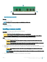
Страница 101: ...necessary to maintain proper thermal conditions WARNING The heat sink may be hot to touch for some time after the system has been powered down Allow the heat sink to cool before removing it 1 Follow the safety guidelines listed in Safety instructions 2 If installed remove the processor DIMM blank and CPU dust cover The procedure to remove the processor DIMM blank is similar to that of the memory m...

Страница 102: ...ble install the air shroud NOTE If applicable open the PCIe card holder latch on the air shroud to install the full length card 2 Follow the procedure listed in After working inside your system Related links Opening and closing the PCIe card holder latch Installing the air shroud Expansion cards and expansion card risers An expansion card in the system is an add on card that can be inserted into a...

Страница 103: ...length Processor 1 Slot 3 x8 full height half length Processor 1 Riser configuration 3 1A 2A Two x8 and three x16 slots Slot 1 x16 full height full length Processor 1 Slot 4 x16 full height full length Processor 2 N A N A N A N A Slot 5 x8 full height full length Processor 2 Slot 3 x16 full height half length Processor 1 Slot 6 x8 low profile half length Processor 1 Riser configuration 4 1A 2A 3A ...

Страница 104: ... length Processor 1 Slot 6 x8 low profile half length Processor 1 Table 43 Riser configurations with 4 PCIe slots Riser configuration 1 1B 2B and Riser configuration 2 1B 2C Card Type Slot priority Maximum number of cards GPU double width N A N A GPU single width N A N A PCIe Bridge 4 1 Internal storage adapter 4 1 Express Flash NVMe PCIe SSD adapter 1 2 3 4 4 HCA EDR 4 1 100 GB NIC 4 1 100 G OPA ...

Страница 105: ...3 100 GB NIC 1 8 4 3 100 G OPA 1 8 4 3 HCA FDR 6 1 40 GB NIC 7 2 3 5 1 8 4 7 40 GB NIC 6 1 HBA FC32 7 2 3 5 1 8 4 7 HBA FC32 6 1 25 GB NIC 7 2 3 5 1 8 4 3 25 GB NIC 6 1 HBA FC16 7 2 3 5 1 8 4 7 HBA FC16 6 1 10 GB NIC 7 2 3 5 1 8 4 7 10 GB NIC 6 1 HBA FC8 7 2 3 5 1 8 4 7 HBA FC8 6 1 1 GB NIC 7 2 3 5 1 8 4 7 1 GB NIC 6 1 External storage adapter 7 2 3 5 1 8 4 7 External storage adapter 6 1 BOSS 7 2 ...

Страница 106: ... installed Since NVDIMM N battery is installed on the GPU shroud GPUs are not supported on riser 2 Opening and closing the PCIe card holder latch Before installing or removing a full length PCIe card the PCIe card holder latch must be closed When the full length PCIe card is installed open the PCIe card holder latch Prerequisites 1 Follow the safety guidelines listed in Safety instructions 2 Follo...

Страница 107: ...e your system 3 If applicable remove the air shroud 4 If applicable disconnect the cables from the expansion card 5 When removing a card from riser 2 or 3 ensure that the PCIe card holder latch is closed Steps 1 Pull the expansion card latch out of the slot 2 Hold the expansion card by its edges and pull the card until the card edge connector disengages from the expansion card connector on the ris...

Страница 108: ...ng the expansion card from expansion card riser 1 Figure 54 Removing the expansion card from expansion card riser 2B 108 Dell EMC PowerEdge R740 Installation and Service Manual Installing and removing system components ...
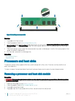
Страница 109: ...tal filler bracket over the empty expansion slot opening and push the expansion card latch NOTE You must install a filler bracket over an empty expansion card slot to maintain Federal Communications Commission FCC certification of the system The brackets also keep dust and dirt out of the system and aid in proper cooling and airflow inside the system Dell EMC PowerEdge R740 Installation and Servic...

Страница 110: ...led remove the filler bracket NOTE Store the filler bracket for future use Filler brackets must be installed in empty expansion card slots to maintain Federal Communications Commission FCC certification of the system The brackets also keep dust and dirt out of the system and aid in proper cooling and airflow inside the system 3 Hold the card by its edges and align the card edge connector with the ...

Страница 111: ...alling expansion card into expansion card riser 2B Figure 59 Installing expansion card into expansion card riser 2 Dell EMC PowerEdge R740 Installation and Service Manual Installing and removing system components 111 ...

Страница 112: ...ning and closing the PCIe card holder latch Installing the air shroud Removing riser 2 and 3 blank Prerequisites 1 Follow the safety guidelines listed in Safety instructions 2 Follow the procedure listed in Before working inside your system 3 Remove the air shroud Steps 1 Using Phillips 2 screwdriver loosen the screws 3 that secure the blank to the system 2 Press the release tab and holding the bl...

Страница 113: ...ollow the safety guidelines listed in Safety instructions Steps 1 Align the screw and guide rail on the riser blank with the screw hole and standoff on the system 2 Lower the blank into the system until the release tab clicks into place 3 Tighten the screws to secure the riser blank to the system Dell EMC PowerEdge R740 Installation and Service Manual Installing and removing system components 113 ...

Страница 114: ...ing riser 3 blank Prerequisites 1 Follow the safety guidelines listed in Safety instructions 2 Follow the procedure listed in Before working inside your system Steps 1 Using Phillips 2 screwdriver loosen the screw that secures the blank to the system 2 Lift the blank away from the system 114 Dell EMC PowerEdge R740 Installation and Service Manual Installing and removing system components ...

Страница 115: ...ank Prerequisites Follow the safety guidelines listed in Safety instructions Steps 1 Align the screw on the riser with the screw hole on the system 2 Using Phillips 2 screwdriver tighten the screw to secure the blank to the system Dell EMC PowerEdge R740 Installation and Service Manual Installing and removing system components 115 ...

Страница 116: ...d in Safety instructions 2 Follow the procedure listed in Before working inside your system 3 If installed remove the expansion cards from the riser 4 Disconnect any cables connected to the riser Steps Press the release latches and lift the riser from the riser connector on the system board 116 Dell EMC PowerEdge R740 Installation and Service Manual Installing and removing system components ...
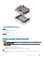
Страница 117: ...ling expansion card riser 1 Prerequisites Follow the safety guidelines listed in Safety instructions Steps 1 Align the guide rails on the riser with the standoffs on the side of the system 2 Lower the riser into the system until the riser connector engages with the connector on the system board Dell EMC PowerEdge R740 Installation and Service Manual Installing and removing system components 117 ...
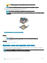
Страница 118: ...2 Follow the procedure listed in Before working inside your system 3 If applicable close the PCIe card holder latch on the air shroud to release the full length card 4 If installed remove expansion cards installed on the riser 5 Remove the air shroud 6 Disconnect any cables connected to the riser Steps 1 To remove expansion card riser 2A a Using Phillips 2 screwdriver loosen the screws that secure...

Страница 119: ...ansion card riser 2 Next steps Install the expansion card riser 2 Related links Removing the expansion card from expansion card riser Removing the air shroud Installing expansion card riser 2 Installing expansion card riser 2 Prerequisites Follow the safety guidelines listed in Safety instructions Dell EMC PowerEdge R740 Installation and Service Manual Installing and removing system components 119...

Страница 120: ...e system Figure 69 Installing expansion card riser 2A 2 To install expansion card riser 2B or 2C a Align the slot on the riser with the standoff on the system b Lower the riser into the system until the riser card connector engages with the connector on the system board Figure 70 Installing expansion card riser 2 Next steps 1 Install the air shroud 2 If removed install the expansion cards into the...

Страница 121: ...ng inside your system 3 Remove the air shroud NOTE If applicable close the PCIe card holder latch on the air shroud to release the full length card 4 If installed remove expansion cards installed on the riser 5 Disconnect any cables connected to the riser card Steps 1 Using Phillips 2 screwdriver loosen the screw that secures the riser to the system 2 Press the release tab and holding the riser by...

Страница 122: ...Installing expansion card riser 3 Next steps 1 If removed install expansion cards into the riser 2 Install the air shroud NOTE If applicable open the PCIe card holder latch on the air shroud to install the full length card 3 Follow the procedure listed in After working inside your system 4 Install any device drivers required for the card as described in the documentation for the card Related links...

Страница 123: ...afety instructions 2 Follow the procedure listed in Before working inside your system 3 Remove the top cover of the GPU air shroud Steps 1 Lift the expansion card latch 2 Close the PCIe card holder latch on the GPU air shroud and risers 3 Hold the GPU card by its edges and slide out the GPU card at an angle to release it from the connector on the riser card 4 Disconnect the cable from the GPU card...

Страница 124: ...rd into the riser slot until it is fully seated 7 Locate the GPU power connectors on the cable and plug them to the six pin and eight pin connectors on the GPU card 8 Press down on the GPU card lock to secure the card in position NOTE Ensure that the GPU card is seated into the PCIe card holder latch 9 Open the PCIe card holder latch NOTE Nvidia FF20 and FF30 GPU cards cannot engage with the PCIe ...

Страница 125: ...he SD card connector on the internal dual SD module Orient the SD card appropriately and insert the contact pin end of the card into the slot NOTE The slot is keyed to ensure correct insertion of the card 2 Press the card into the card slot to lock it into place Next steps Follow the procedure listed in After working inside your system Removing the optional IDSDM vFlash card Prerequisites 1 Follow...

Страница 126: ...ing the optional IDSDM vFlash card Prerequisites Follow the safety guidelines listed in Safety instructions Steps 1 Locate the IDSDM vFlash connector on the system board To locate IDSDM vFlash see the System board jumpers and connectors section 2 Align IDSDM vFlash card with the connector on the system board 3 Push IDSDM vFlash card until it is firmly seated on the system board 126 Dell EMC PowerE...

Страница 127: ...he micro SD card Installing expansion card into expansion card riser Network daughter card The network daughter card NDC is a small removable mezzanine card which provides the flexibility of selecting different network connectivity options CAUTION If the GPU card is installed you cannot install the 10 GbE NDC Removing the network daughter card Prerequisites 1 Follow the safety guidelines listed in...

Страница 128: ...rd Next steps Install the NDC Related links Removing expansion card riser 2 Installing the network daughter card Installing the network daughter card Prerequisites Follow the safety guidelines listed in Safety instructions Steps 1 Orient the NDC so that the Ethernet connectors fit through the slot in the chassis 2 Align the captive screws at the back end of the card with the screw holes on the sys...

Страница 129: ... controller supports SAS and SATA hard drives and also enables you to set up the hard drives in RAID configurations as supported by the version of the storage controller Removing integrated storage controller card Prerequisites 1 Follow the safety guidelines listed in Safety instructions 2 Follow the procedure listed in Before working inside your system 3 Remove the air shroud 4 Remove the expansi...

Страница 130: ...ard by its edges and pull the board until the connector on the board disengages from the connector on the system board Figure 78 Removing integrated storage controller card Next steps Install the integrated storage controller card Related links Removing the air shroud Removing expansion card riser 1 Installing integrated storage controller card 130 Dell EMC PowerEdge R740 Installation and Service ...

Страница 131: ... integrated storage controller card holder on the system board 4 Lower the card into place until the card is fully seated in the integrated storage controller card holder Figure 79 Installing integrated storage controller card 5 Align the screws on the integrated storage controller card cable with the screw holes on the system board 6 Using Phillips 2 screwdriver tighten the screws to secure the i...

Страница 132: ...options for PowerEdge R740 systems System Supported backplane options PowerEdge R740 2 5 inch x16 SAS SATA backplane or 2 5 inch x8 SAS SATA backplane or 3 5 inch x8 SAS SATA backplane NOTE Mixing of 2 5 inch 10K or 15K SAS hard drives with 2 5 inch 7 2K SATA or Nearline SAS hard drives in the same backplane is not supported Hard drive backplane connectors Figure 81 Back view of 16 x 2 5 inch hard...

Страница 133: ...e the hard drives from the system before removing the backplane CAUTION Note the number of each hard drive and temporarily label them before you remove the hard drive so that you can replace them in the same locations 1 Follow the safety guidelines listed in Safety instructions 2 Follow the procedure listed in Before working inside your system 3 Remove the air shroud 4 Remove the cooling fan assem...

Страница 134: ...nstalling hard drive backplane The procedure to install the backplane is identical for all backplane configurations Prerequisites Follow the safety guidelines listed in Safety instructions Steps 1 Use the hooks on the system as guides to align the hard drive backplane 2 Lower the hard drive backplane until the release tabs snap into place 134 Dell EMC PowerEdge R740 Installation and Service Manual...

Страница 135: ... Install the cooling fan assembly 5 Install the air shroud 6 Follow the procedure listed in After working inside your system Related links Installing a hard drive Installing the backplane cover Installing the cooling fan assembly Installing the air shroud Dell EMC PowerEdge R740 Installation and Service Manual Installing and removing system components 135 ...

Страница 136: ... 5 inch hard drive backplane with mini PERC 1 backplane 2 backplane signal cable 3 backplane power cable 4 system board 5 mini PERC 6 SAS cable 136 Dell EMC PowerEdge R740 Installation and Service Manual Installing and removing system components ...
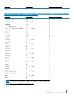
Страница 137: ...rd drive backplane with adapter PERC 1 backplane 2 backplane signal cable 3 backplane power cable 4 system board 5 adapter PERC 6 SAS cable Dell EMC PowerEdge R740 Installation and Service Manual Installing and removing system components 137 ...

Страница 138: ... drive backplane with on board SATA 1 backplane 2 backplane power cable 3 backplane signal cable 4 system board 5 SATA B cable 6 SATA A cable 138 Dell EMC PowerEdge R740 Installation and Service Manual Installing and removing system components ...
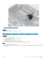
Страница 139: ... hard drive backplane with mini PERC 1 backplane 2 backplane power cable 3 backplane signal cable 4 system board 5 mini PERC 6 SAS cable Dell EMC PowerEdge R740 Installation and Service Manual Installing and removing system components 139 ...

Страница 140: ... backplane with adapter PERC 1 backplane 2 backplane power cable 3 backplane signal cable 4 system board 5 adapter PERC 6 SAS A cable 7 SAS B cable 140 Dell EMC PowerEdge R740 Installation and Service Manual Installing and removing system components ...

Страница 141: ...e backplane with mini PERC 1 backplane 2 backplane expander 3 backplane power cable 4 backplane signal cable 5 system board 6 mini PERC 7 SAS cable Dell EMC PowerEdge R740 Installation and Service Manual Installing and removing system components 141 ...

Страница 142: ... with the same or equivalent type recommended by the manufacturer For more information see the safety information that shipped with your system 1 Follow the safety guidelines listed in Safety instructions 2 Follow the procedure listed in Before working inside your system 3 If applicable close the PCIe card holder latch on the air shroud to release the full length card 4 If applicable disconnect th...

Страница 143: ...Follow the procedure listed in After working inside your system 5 While booting press F2 to enter the System Setup and ensure that the battery is operating properly 6 Enter the correct time and date in the System Setup Time and Date fields 7 Exit the System Setup Related links System board jumpers and connectors Opening and closing the PCIe card holder latch Removing expansion card riser 1 Install...

Страница 144: ...ou remove them from the system board Route these cables properly when you replace them to prevent them from being pinched or crimped Steps 1 Disconnect the cables from the system board 2 Using Phillips 2 screwdriver loosen the screw on the USB 3 0 module 3 Slide the USB 3 0 module out of the system Figure 95 Removing USB 3 0 module Next steps Install the USB 3 0 module Related links Removing the b...

Страница 145: ... Route and connect the USB cable to internal USB port and power cable to the backplane 3 power connector on the system board To locate the connector see the System board jumpers and connectors section Figure 96 Installing USB 3 0 module Next steps 1 Install the internal USB memory key 2 Install the air shroud 3 Install the cooling fan assembly 4 Install the backplane cover 5 Follow the procedure l...

Страница 146: ... key are 15 9 mm wide x 57 15 mm long x 7 9 mm high 1 Follow the safety guidelines listed in Safety instructions 2 Follow the procedure listed in Before working inside your system Steps 1 Locate the USB port or USB memory key on the system board To locate the USB port see the Internal USB memory key optional section 2 If installed remove the USB memory key from the USB port 3 Insert the replacemen...

Страница 147: ...se tab to release the optical drive 2 Slide the optical drive out of the system Figure 97 Removing the optional optical drive Next steps 1 If you are not adding a new optical drive install the optical drive blank The procedure to install the optical drive blank is the same as the optical drive 2 Install the optional optical drive Related links Removing the backplane cover Removing the air shroud I...

Страница 148: ... Install the backplane cover 4 Follow the procedure listed in After working inside your system Related links Installing the air shroud Installing the backplane cover Power supply units The power supply unit PSU is an internal hardware component which supplies power to the components in the system Your system supports one of the following Two 2000 W 1600 W 1100 W 750 W or 495 W AC PSUs Two 1100 W D...

Страница 149: ...PSU supports 100 percent of the system load thus operating at higher efficiency The PSU in the sleep state monitors output voltage of the active PSU If the output voltage of the active PSU drops the PSU in the sleep state returns to an active output state If having both PSUs active is more efficient than having one PSU in the sleep state the active PSU can also activate the sleeping PSU The defaul...

Страница 150: ...ing a power supply unit The procedure for removing AC and DC PSUs is identical Prerequisites CAUTION The system needs one power supply unit PSU for normal operation On power redundant systems remove and replace only one PSU at a time in a system that is powered on 1 Follow the safety guidelines listed in Safety instructions 2 Disconnect the power cable from the power source and from the PSU you in...

Страница 151: ... Installing a power supply unit The procedure for installing AC and DC PSUs is identical Prerequisites 1 Follow the safety guidelines listed in Safety instructions 2 For systems that support redundant PSU ensure that both the PSUs are of the same type and have the same maximum output power NOTE The maximum output power shown in watts is listed on the PSU label Steps Slide the PSU into the system u...

Страница 152: ...ctrician must perform all connections to DC power and to safety grounds Do not attempt connecting to DC power or installing grounds yourself All electrical wiring must comply with applicable local or national codes and practices Damage due to servicing that is not authorized by Dell is not covered by your warranty Read and follow all safety instructions that came with the product CAUTION Wire the ...

Страница 153: ...ately 4 5 mm 0 175 inch of copper wire 2 Using a hand crimping tool Tyco Electronics 58433 3 or equivalent crimp the ring tongue terminal Jeeson Terminals Inc R5 4SA or equivalent to the green and yellow wire safety ground wire 3 Connect the safety ground wire to the grounding post on the back of the system by using a 6 32 nut equipped with a locking washer Assembling DC input power wires Prerequi...

Страница 154: ...d TPM plug in module breaks the cryptographic binding and it cannot be re installed or installed on another system board 1 Follow the safety guidelines listed in Safety instructions 2 Follow the procedure listed in Before working inside your system 3 Remove the following a Air shroud b Cooling fan assembly c Power supply unit s d All expansion card risers e Integrated storage controller card f iDS...

Страница 155: ...ory module Removing the network daughter card Installing system board Installing system board Prerequisites Follow the safety guidelines listed in Safety instructions Steps 1 Unpack the replacement system board assembly CAUTION Do not lift the system board by holding a memory module processor or other components CAUTION Take care not to damage the system identification button while placing the sys...

Страница 156: ... NOTE Ensure that the cables inside the system are routed along the chassis wall and secured using the cable securing bracket 4 Follow the procedure listed in After working inside your system 5 Ensure that you a Use the Easy Restore feature to restore the Service Tag For more information see the Easy restore section b If the Service Tag is not backed up in the backup flash device enter the Service...

Страница 157: ...iDRAC Enterprise license For more information see the Integrated Dell Remote Access Controller User s Guide at Dell com idracmanuals Restoring the Service Tag by using the Easy Restore feature By using the Easy Restore feature you can restore your Service Tag license UEFI configuration and the system configuration data after replacing the system board All data is automatically backed up in a backu...

Страница 158: ...teps 1 Locate the TPM connector on the system board NOTE To locate the TPM connector on the system board see the System board jumpers and connectors section 2 Press to hold the module down and remove the screw using the security Torx 8 bit shipped with the TPM module 3 Slide the TPM module out from its connector 4 Push the plastic rivet away from the TPM connector and rotate it 90 counterclockwise...

Страница 159: ...ter System Setup 2 On the System Setup Main Menu screen click System BIOS System Security Settings 3 From the TPM Security option select On 4 Save the settings 5 Restart your system 6 Enter System Setup again 7 On the System Setup Main Menu screen click System BIOS System Security Settings 8 Select the TPM Advanced Settings option 9 From the TPM2 Algorithm Selection option select SHA256 then go ba...

Страница 160: ...panel cable from the system board connector 2 Using Phillips 1 screwdriver remove the screws to remove the cable cover which secure the control panel and cable tube to the system 3 Holding the control panel and cable tube by its sides remove the control panel and cable tube away from the system Figure 106 Removing left control panel Next steps Install the left control panel Related links Removing ...

Страница 161: ... the cooling fan assembly Removing the right control panel Prerequisites 1 Follow the safety guidelines listed in Safety instructions 2 Follow the procedure listed in Before working inside your system NOTE Ensure that you note the routing of the cables as you remove them from the system board You must route the cables properly when you replace them to prevent the cables from being pinched or crimp...

Страница 162: ...idelines listed in Safety instructions Steps 1 Route the control panel cable and VGA cable through the side wall of the system 2 Align the control panel with the control panel slot on the system and attach the control panel to the system 3 Connect the VGA cable to the system board 4 Connect the control panel cable to the system board and secure it using cable latch 5 Using Phillips 1 screwdriver i...

Страница 163: ...n assembly 2 Install the air shroud 3 Follow the procedure listed in After working inside your system Related links Installing the cooling fan assembly Installing the air shroud Dell EMC PowerEdge R740 Installation and Service Manual Installing and removing system components 163 ...

Страница 164: ...us messages that inform you if tests are completed successfully View error messages that inform you of problems encountered during testing Running the Embedded System Diagnostics from Boot Manager Run the Embedded System Diagnostics ePSA if your system does not boot 1 When the system is booting press F11 2 Use the up arrow and down arrow keys to select System Utilities Launch Diagnostics 3 Alterna...

Страница 165: ...lays the results of all tests that are run System health Provides the current overview of the system performance Event log Displays a time stamped log of the results of all tests run on the system This is displayed if at least one event description is recorded Dell EMC PowerEdge R740 Installation and Service Manual Using system diagnostics 165 ...

Страница 166: ...he various boards in the system Jumpers on the system board help to disable the system and setup passwords You must know the connectors on the system board to install components and cables correctly Topics System board jumpers and connectors System board jumper settings Disabling forgotten password 8 166 Dell EMC PowerEdge R740 Installation and Service Manual Jumpers and connectors ...

Страница 167: ...on 1 J_ODD Optical drive power connector 2 A7 A1 A8 A2 A9 A3 Memory module sockets 3 J_FAN2U_6 Cooling fan 6 connector 4 J_BP3 Backplane 3 power connector 5 J_FAN2U_5 Cooling fan 5 connector 6 A6 A12 A5 A11 A4 A10 Memory module sockets 7 J_FAN2U_4 Cooling fan 4 connector Dell EMC PowerEdge R740 Installation and Service Manual Jumpers and connectors 167 ...

Страница 168: ...3 PCIe 225 W power 22 J_BP2 RSR2_225W Backplane 2 power connector Riser 2 PCIe 225 W power 23 J_BATT_SIG NVDIMM N battery signal connector 24 J_BATT_PWR NVDIMM N battery power connector 25 J_USB_INT Internal USB connector 26 J_IDSDM IDSDM vFlash connector 27 J_NDC NDC connector 28 J_R2_X24_IT9 Riser 2 connector 29 J_R2_3R_X8_IT9 Riser 2 connector 30 BATTERY Battery connector 31 J_FRONT_VIDEO Video...

Страница 169: ...d by Dell is not covered by your warranty Read and follow the safety instructions that are shipped with your product Steps 1 Turn off the system including any attached peripherals and disconnect the system from the electrical outlet 2 Remove the system cover 3 Move the jumper on the system board jumper from pins 2 and 4 to pins 4 and 6 4 Install the system cover The existing passwords are not disa...

Страница 170: ...Related links Removing the system cover Installing the system cover 170 Dell EMC PowerEdge R740 Installation and Service Manual Jumpers and connectors ...

Страница 171: ...ent c Select your product The support page that lists the various support categories is displayed 5 For contact details of Dell Global Technical Support a Click Global Technical Support b The Contact Technical Support page is displayed with details to call chat or e mail the Dell Global Technical Support team Documentation feedback You can rate the documentation or write your feedback on any of ou...

Страница 172: ...upportAssist application in your IT environment you can receive the following benefits Automated issue detection SupportAssist monitors your Dell devices and automatically detects hardware issues both proactively and predictively Automated case creation When an issue is detected SupportAssist automatically opens a support case with Dell Technical Support Automated diagnostic collection SupportAssi...

Отзывы: