170
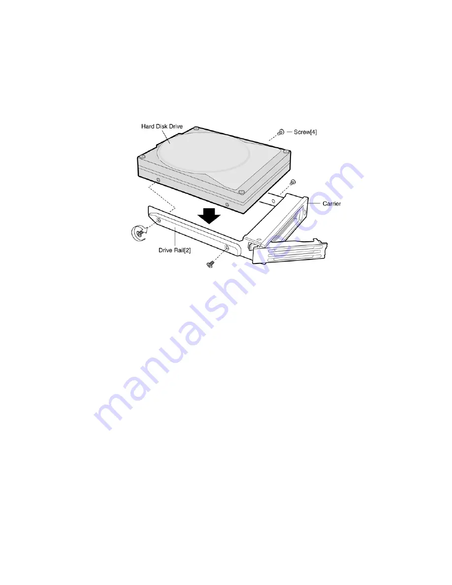
7. Position the carrier as shown in Figure 56.
8. Place the drive in the carrier with the drive label-side up and the SCA (80 Pin) SCSI connector
end of the drive facing the back of the carrier.
9. Align the holes in the drive to the holes in the drive carrier and drive rails. Insert the mounting
screws that were removed in the previous steps to and secure the carrier to the drive.
10. Continue with the instructions under Installing a Hard Drive.
Figure 56. Attaching the Hard Drive to the Carrier
Installing a Hard Drive
1. With the drive carrier handle open fully, place the drive carrier into the peripheral drive bay.
2. Slide the drive carrier all the way into the drive bay.
3. Using the drive carrier handle, firmly push the assembly into the bay until the drive docks with
the SCSI backplane connector.
4. Swing the drive carrier handle closed until it latches.
Hot-swap System Fans
The six (60x60x38-mm) cooling fans provide 50 CFM of airflow each. The server system supports
only a fully populated system fan configuration. However, the server system will continue to meet
the thermal specifications if a fan fails. The six fans are mounted side-by-side in the fan bay across
the center section of the chassis. The fans can be hot-swapped; they can be removed and re-
installed without turning the server system power off.
The procedures in this section describe how to identify a failed fan and replace a failed fan. See
Cooling Subsystem for more information about the operation of the system fans.
Содержание 3250
Страница 1: ...Dell TM PowerEdge TM 3250 SR870BH2 Systems Product Guide Model Code SVS ...
Страница 22: ...22 ...
Страница 229: ...229 Safety Warnings WARNING English US AVERTISSEMENT Français WARNUNG Deutsch AVVERTENZA Italiano ADVERTENCIAS Español ...
Страница 240: ......


