background image

AC or DC power supply replacement

CAUTION:

 Disconnect the power cable before removing the power supplies. Also, disconnect all power cables before

servicing.

NOTE:

 The PSU slides into the slot smoothly. Do not force a PSU into a slot as this action may damage the PSU or the

N2200-ON Series switch.

NOTE:

 If a PSU fails, you must replace the entire unit. There are no field serviceable components in the PSU. To request

a hardware replacement, see 

www.dell.com/support/

.

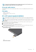
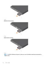
1. Disconnect the power cable from the PSU.
2. Use the grab handle to slide the PSU out of the power supply bay.
3. Use the grab handle on the replacement PSU to slide it into the power supply bay.
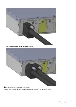
4. Attach the power cable to the replacement PSU.

NOTE:

 The switch powers up when the cables are connected between the power supply and the power source.

DC power connections

Each DC PSU comes with a connector cable. One cable is provided for each DC PSU.

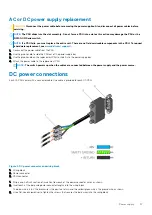
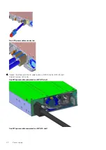
Figure 4. DC power connector and wiring block

1. Wiring block
2. Power connector
3. PSU connector

1. Strip a one-half inch section of insulation from each of the power connector wires, as shown.
2. Insert each of the bare wire power connector lengths into the wiring block.

The blue wire is -48 V, the black wire is the positive return, and the yellow/green wire is the ground wire, as shown.

3. Use a flat-head screwdriver to tighten the screws that secures the bare wires into the wiring block.

Power supply

37

Содержание PowerSwitch N2200-ON Series

Страница 1: ...Dell EMC PowerSwitch N2200 ON Series Installation Guide...

Страница 2: ...l damage to hardware or loss of data and tells you how to avoid the problem WARNING A WARNING indicates a potential for property damage personal injury or death 2020 Dell Inc or its subsidiaries All r...

Страница 3: ...Series switch installation 20 Unpack 20 Unpacking Steps 20 Rack or cabinet hardware installation 21 Ground cable 21 Desktop 22 Two post five inch offset switch installation 22 Two post flush mount swi...

Страница 4: ...operating system 49 Check your switch 50 Uninstall an existing OS 51 Install a NOS 51 Automatic NOS installation 52 Manual NOS installation 53 9 Specifications 54 Chassis physical design 54 IEEE stand...

Страница 5: ...display workplaces This device is not intended for use in the direct field of view at visual display workplaces To avoid incommoding reflections at visual display workplaces this device must not be pl...

Страница 6: ...OTE For the most recent documentation see Dell EMC support www dell com support Information symbols This book uses the following information symbols NOTE The Note icon signals important operational in...

Страница 7: ...ts 2 5G BASE T 10M 100M 1G 2 5G RJ45 multigigabit ports 1 12 ports 802 3at 30W PoE 13 24 ports 802 3bt Type 3 60W PoE 4 ports 25G SFP28 2 ports 40G QSFP stacking 2 pluggable AC PSUs 1 default and 1 op...

Страница 8: ...1 Luggage tag 2 2 5GBASE T RJ45 ports First 12 ports with 802 at 30W PoE Second 12 ports with 802 3bt Type 3 60W PoE 3 RJ45 serial management port 4 RJ45 Ethernet console port 5 USB Type A port 6 Stac...

Страница 9: ...60W PoE 3 RJ45 serial management port 4 RJ45 Ethernet console port 5 USB Type A port 6 Stack ID 7 MicroUSB Type B port 8 Status LEDs 9 25G SFP28 ports N2200 ON Series PSU side views N2224X ON PSU sid...

Страница 10: ...P28 and two ports of 40G QSFP for stacking N2248PX ON 1 U 48 multigigabit ports 2 5GBASE T RJ24 24 ports of 802 3at 30W PoE and 24 ports of 802 3bt Type 3 60W PoE four ports 25G SFP28 and two ports of...

Страница 11: ...e of the switch This section describes open networking installation environment ONIE LED behaviors Some LED behaviors may change after you install your software LED behavior The following N2200 ON Ser...

Страница 12: ...ering airflows missing a fan or fan tray not functioning properly LOCATOR LED System Beacon Off Locator function disabled Flashing blue Locator function enabled Table 3 1000MBase T and 10 100MBase T P...

Страница 13: ...autonegotiated forced to 10 100 1000MBase T Activity LED Off No activity Flashing green 30ms Port activity Table 7 SFP28 port LEDs LED Description Link LED All four LEDs Off No link Solid green Link...

Страница 14: ...able AC or DC PSUs optional one EPS and two fan subsystem N2248X ON one U 48 ports 2 5GBASE T RJ24 four ports 25G SFP28 two 40G ports QSFP for stacking two pluggable AC or DC PSUs and three fan subsys...

Страница 15: ...he back of the luggage tag includes a QRL that takes you to a How To site where you can watch videos about racking the switch replacing components configuring port channels and so on N2224PX ON and N2...

Страница 16: ...1 Product ID QRL 2 Product information QRL 3 SVC tag 4 MAC address 5 Exp Svc code 16 N2200 ON Series switch...

Страница 17: ...to 95 percent RH noncondensing In a dry clean well ventilated and temperature controlled room away from heat sources such as hot air vents or direct sunlight Away from sources of severe electromagnet...

Страница 18: ...ilation position the switch in an equipment rack or cabinet with a minimum of 5 inches 12 7 cm of clearance around the exhaust vents When you install two N2200 ON switches near each other to permit pr...

Страница 19: ...vironment NOTE ESD damage can occur when components are mishandled Always wear an ESD preventive wrist or heel ground strap when handling the N2200 ON Series switch and accessories After you remove th...

Страница 20: ...placement Switch replacement Unpack NOTE Before unpacking the switch inspect the container and immediately report any evidence of damage When unpacking the switch ensure that the following items are i...

Страница 21: ...n of the equipment is not compromised Reliable earthing Maintain reliable earthing of rack mounted equipment Pay particular attention to the supply connections other than the direct connections to the...

Страница 22: ...h over and place on a desktop Two post five inch offset switch installation NOTE To install an external power supply EPS see the External Power Supply EPS Installation for the Dell EMC PowerSwitch N22...

Страница 23: ...ly EPS Installation for the Dell EMC PowerSwitch N2200 ON and N3200 ON Series Switches at www dell com support 1 Locate the included mounting brackets and screws 2 Insert the mounting brackets onto th...

Страница 24: ...200 ON Series Switches at www dell com support You must order the mounting supplies for this installation separately You need a drill and a pencil to complete this procedure 1 Remove the four wall or...

Страница 25: ...al into the anchors leaving approximately 5 mm 0 20 in gap between the anchor and the screw 8 Slide the switch onto the screws and tighten the screws to secure the switch in place Torque the screws to...

Страница 26: ...ded round hole methods The tooled installation methods include two post flush mount two post center mount or four post threaded mount NOTE You must order the ReadyRails mounting supplies for this inst...

Страница 27: ...lace one rail between the left and right vertical posts Align and seat the back flange rail pegs in the back vertical post flange The center extractions show how the pegs appear in both the square and...

Страница 28: ...latch castings for future rack requirements It is not necessary to remove the back flange castings 2 Attach one rail to the front post flange with two user supplied screws item 2 3 Slide the plunger b...

Страница 29: ...on instructions see the installation labels attached to the rail assembly 1 Remove the tool less latch castings from the front side of each ReadyRails assembly as shown in the following figure Use a t...

Страница 30: ...otection Never look directly into the end of a terminated or unterminated fiber or connector as it may cause eye damage 1 Position the optic to enter the port correctly The optic has a key that preven...

Страница 31: ...s and Downloads page for your switch at www dell com support Switch replacement The following steps describe removing and replacing a switch with an identical replacement switch For further assistance...

Страница 32: ...the replacement switch software using the procedure included with the firmware download 11 Copy the backed up switch configuration to the new switch copy tftp hostip filepath running config NOTE For f...

Страница 33: ...your equipment correctly excessive emissions may result Use a qualified electrician to ensure that the power cables meet your local electrical requirements WARNING Equipment that provides DC input to...

Страница 34: ...s PSU1 is near the center of the switch PSU2 is on the right edge of the switch The PSU has an integrated fan which you cannot replace individually if the fan integrated in a PSU fails you must replac...

Страница 35: ...e switch NOTE Ensure that you correctly install the PSU When you install the PSU correctly the power connector is on the left side of the PSU 1 Remove the PSU slot cover from the N2200 ON Series switc...

Страница 36: ...PSU N2248PX ON PSU installation 1 PSU N2248X ON PSU installation 1 PSU NOTE The N2200 ON Series switch powers up when you connect the cables between the power supply and the power source 36 Power supp...

Страница 37: ...lacement PSU to slide it into the power supply bay 4 Attach the power cable to the replacement PSU NOTE The switch powers up when the cables are connected between the power supply and the power source...

Страница 38: ...the EPS shelf NOTE For more information about the external power supply EPS see External Power Supply EPS Installation for the Dell EMC PowerSwitch N2200 ON and N3200 ON Series Switches at www dell co...

Страница 39: ...MPS 3S shelf 3 Connect the EPS power cable to the EPS DC In on the switch Torque the screw to 10 in lbs One EPS power cable connected Power supply 39...

Страница 40: ...ted 4 Connect the other end of the DC cable to either a MPS 1S shelf or MPS 3S shelf Torque the screw to 10 in lbs One EPS power cable connected to a MPS 1S shelf One EPS power cable connected to a MP...

Страница 41: ...EPS power cables connected to a MPS 3S shelf 5 Repeat until all EPS power cables are connected To disconnect an EPS power cable unscrew the cable and disconnect the cable from the switch Power supply...

Страница 42: ...ow is only supported on the N2224X ON and N2248X ON AC switches All fans and PSUs in a configuration must be in the same airflow direction Environmental factors can decrease the amount of time that is...

Страница 43: ...itch Fan LEDs Solid green Fan input is OK Flashing green blink at 1Hz Fan is in a faulty state Off Fan is off Fan module installation The fan module in the N2200 ON Series switch is field replaceable...

Страница 44: ...1 Fan N2224X ON fan installation 1 Fan N2248PX ON fan installation 1 Fan N2248X ON fan installation 44 Fans...

Страница 45: ...ement To request a hardware replacement see www dell com support 1 Take the replacement fan module out of the shipping box 2 Slide the installed fan module out of the bay 3 Slide the replacement modul...

Страница 46: ...Ensure that any equipment that is attached to the serial port can support the required 115200 baud rate NOTE If the serial port of your computer cannot accept a female DB 9 connector use a DB 9 to USB...

Страница 47: ...al support for assistance 1 Start up the computer 2 Connect the USB Type A end of cable into an available USB port on the computer 3 Connect the microUSB Type B end of cable into the microUSB Type B c...

Страница 48: ...e device dev sdb number to the mnt usb directory ONIE mount t vfat dev sdb number mnt usb NOTE If the mnt usb directory is missing the following message displays mount mounting dev sdb number on mnt u...

Страница 49: ...s fully operational before booting After POST the switch uses the Grub bootloader To select an entry use the up and down arrow keys Press Enter to select an operating system or enter e to edit the com...

Страница 50: ...PDT 2019 x86_64 ONIE lspci 00 1f 5 Class 0c80 8086 19e0 00 00 0 Class 0600 8086 1980 00 12 0 Class 0880 8086 19ac 00 15 0 Class 0c03 8086 19d0 00 0b 0 Class 0604 8086 19a6 00 18 0 Class 0780 8086 19d3...

Страница 51: ...ckup of the switch configuration off the switch Automatic installation ONIE discovers network information including the Dynamic Host Configuration Protocol DHCP server connects to an image server and...

Страница 52: ...eats until a successful software image installation occurs and reboots the switch ONIE discovery Usage information All ONIE autodiscovery methods download and run only supported default file names suc...

Страница 53: ...r of the software to install The NOS installer image may create multiple partitions during the installation process After the installation process completes the switch automatically reboots into the n...

Страница 54: ...5 lbs 0 79 kg 550W N2224PX ON 14 70 lbs 6 67 kg PSU is 1 95 lbs 0 88 kg 1050W N2248X ON 15 09 lbs 6 845 kg PSU is 1 75 lbs 0 79 kg 550W N2248PX ON 15 77 lbs 7 155 kg PSU is 2 0 lbs 0 90 kg 1600W Rack...

Страница 55: ...at 30W PoE and 24 ports of 802 3bt Type 3 60W PoE Table 13 AC power requirements Parameter Specifications Power supply 100 240 VAC 50 60 Hz Maximum current draw per system 7A 110 VAC and 3 5 A 220 VAC...

Страница 56: ...interference in which case users will be required to take whatever measures necessary to correct the interference at their own expense Properly shielded and grounded cables and connectors must be used...

Страница 57: ...es European Community Contact Dell EMC EMEA Central Dahlienweg 19 66265 Heusweiler Germany Tel 49 172 6802630 Email EMEA Central Sales Japan VCCI compliance for class A equipment Figure 6 Japan VCCI c...

Страница 58: ...r Products Part 1 Equipment Classification Requirements and User s Guide EN 60825 2 Safety of Laser Products Part 2 Safety of Optical Fibre Communication Systems FDA Regulation 21CFR 1040 10 and 1040...

Страница 59: ...ctronic equipment WEEE The Directive determines the framework for the return and recycling of used appliances as applicable throughout the European Union This label is applied to various products to i...

Страница 60: ...click Technical Support To find the service tag number from the ONIE prompt use the onie syseeprom command ONIE onie syseeprom TlvInfo Header Id String TlvInfo Version 1 Total Length 184 TLV Name Code...

Отзывы: