background image

Technical specifications

The technical and environmental specifications of your system are outlined in this section.

Topics:

System dimensions

System weight

Processor specifications

Supported operating systems

System battery specifications

Memory specifications

Hard drives

Mezzanine and Mini Mezzanine slots specifications

Storage controller specifications

Ports and connectors specifications

Video specifications


Environmental specifications

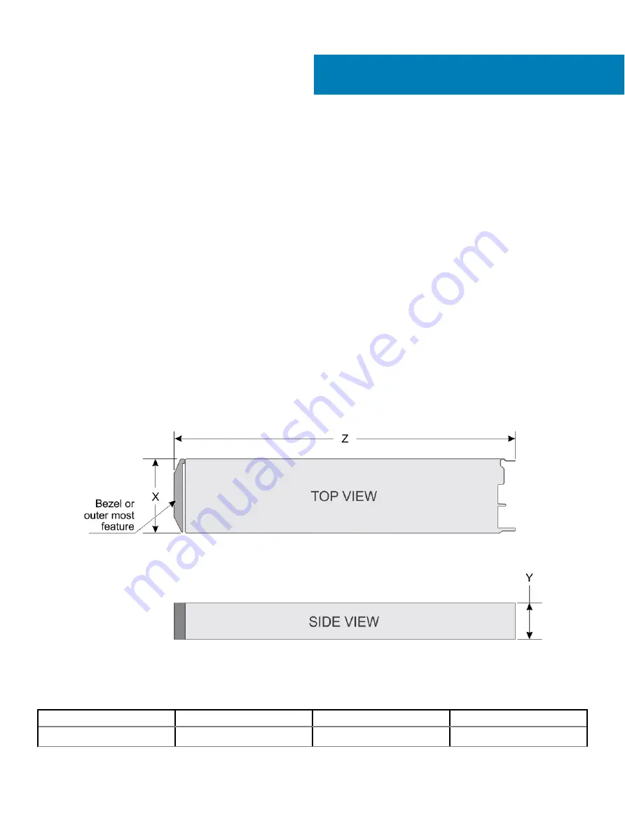
System dimensions

Figure 88. System dimensions

Table 13. System dimensions of thePowerEdge MX740c system

System

X

Y

Z (handle closed).

Dell EMC PowerEdge MX740c

250.2 mm (9.85 inches)

42.15 mm (1.65 inches)

620.35 mm (24.42 inches)

7

Technical specifications

121

Содержание PowerEdge MX740c

Страница 1: ...Dell EMC PowerEdge MX740c Installation and Service Manual Regulatory Model E04B Regulatory Type E04B001 ...

Страница 2: ...amage to hardware or loss of data and tells you how to avoid the problem WARNING A WARNING indicates a potential for property damage personal injury or death 2018 Dell Inc or its subsidiaries All rights reserved Dell EMC and other trademarks are trademarks of Dell Inc or its subsidiaries Other trademarks may be trademarks of their respective owners 2018 12 Rev A01 ...

Страница 3: ...ing system management applications 18 Options to manage the pre operating system applications 18 System Setup 18 Viewing System Setup 18 System Setup details 19 System BIOS 19 iDRAC Settings utility 39 Device Settings 39 Dell Lifecycle Controller 39 Embedded System Management 39 Boot Manager 39 Viewing Boot Manager 39 Boot Manager main menu 40 One shot UEFI Boot menu 40 System Utilities 40 PXE boo...

Страница 4: ...backup unit 65 Removing the BBU from the BBU cage 66 Installing the BBU into the BBU cage 67 Control panel 68 Removing the control panel 68 Installing the control panel 69 System memory 70 General memory module installation guidelines 72 NVDIMM N memory module installation guidelines 73 Mode specific guidelines 74 Removing a memory module 77 Installing a memory module 78 Processors and heat sinks ...

Страница 5: ...al USB memory key 106 Replacing the optional internal USB memory key 106 System battery 107 Replacing the system battery Option A 107 Replacing the system battery Option B 108 System board 110 Removing the system board 110 Installing the system board 112 Trusted Platform Module 115 Upgrading the TPM 115 Initializing TPM for BitLocker users 116 Initializing the TPM 1 2 for TXT users 116 Initializin...

Страница 6: ...temperature 126 Expanded operating temperature 127 Thermal 127 8 System diagnostics and indicator codes 129 Power button LED 129 Drive indicator codes 130 System health and system ID indicator codes 131 Using system diagnostics 131 Dell Embedded System Diagnostics 131 9 Getting help 133 Contacting Dell EMC 133 Documentation feedback 133 Accessing system information by using QRL 133 Quick Resource ...

Страница 7: ... technical specifications diagnostic tools and guidelines to be followed while installing certain components The PowerEdge MX740c is compatible with the PowerEdge MX7000 enclosure For more information about the enclosure refer to the Installation and Service Manual for the PowerEdge MX7000 at Dell com poweredgemanuals 1 About this document 7 ...

Страница 8: ...rs Up to 24 DIMM slots Up to six 2 5 inch SAS SATA HDD SSD or NVMe drives NOTE All instances of SAS NVMe SATA HDDs and SSDs are referred to as drives in this document unless specified otherwise Topics Front view of the system Inside the system Locating the Service Tag of your system System information label 2 8 PowerEdge MX740c sled overview ...

Страница 9: ...iguration 1 USB 3 0 port 2 iDRAC direct port 3 Drives 4 Release handle 5 Release handle button 6 Information tag 7 System health and System ID indicator 8 Power button For more information about the ports see Technical Specifications PowerEdge MX740c sled overview 9 ...

Страница 10: ...ne connector 9 iDRAC card 10 BOSS connector 11 PERC connector Locating the Service Tag of your system The System Information Tab contains the system s unique Express Service Code and Service Tag This information is used by Dell EMC to identify system configuration warranty terms and to route support calls to the appropriate personnel A Quick Resource Locator QRL label on the System Information Tab...

Страница 11: ...Figure 3 Locating Service Tag of your system 1 Information tag 2 Service tag System information label Figure 4 Mechanical overview PowerEdge MX740c sled overview 11 ...

Страница 12: ...Figure 5 Memory information 12 PowerEdge MX740c sled overview ...

Страница 13: ...Figure 6 System board Figure 7 Removal of IDSDM and Internal USB memory key optional PowerEdge MX740c sled overview 13 ...

Страница 14: ...emoval of BBU module and drive cage Figure 9 Removal of backplane and Mezzanine card Figure 10 Removal of PERC cards and Mini Mezzanine card Figure 11 Removal of Jumbo PERC card 14 PowerEdge MX740c sled overview ...

Страница 15: ...nistrators more productive and improve the overall availability of Dell systems iDRAC alerts administrators about system issues and enables them to perform remote system management This reduces the need for physical access to the system Options to set up iDRAC IP address You must configure the initial network settings based on your network infrastructure to enable the communication to and from iDR...

Страница 16: ...ted Dell Remote Access Controller User s Guide at Dell com poweredgemanuals You can also access iDRAC by using RACADM For more information see the RACADM Command Line Interface Reference Guide at Dell com poweredgemanuals Options to install the operating system If the system is shipped without an operating system install the supported operating system by using one of the following resources Table ...

Страница 17: ...manuals Downloading drivers and firmware Dell EMC recommends that you download and install the latest BIOS drivers and systems management firmware on your system Prerequisite Ensure that you clear the web browser cache before downloading the drivers and firmware Steps 1 Go to Dell com support home 2 In the Drivers Downloads section type the Service Tag of your system in the Enter a Service Tag or ...

Страница 18: ... configure the BIOS settings iDRAC settings and Device settings of your system NOTE Help text for the selected field is displayed in the graphical browser by default To view the help text in the text browser press F1 You can access system setup by using two methods Standard graphical browser The browser is enabled by default Text browser The browser is enabled by using Console Redirection Viewing ...

Страница 19: ...em Setup NOTE If your operating system begins to load before you press F2 wait for the system to finish booting and then restart your system and try again 3 On the System Setup Main Menu screen click System BIOS System BIOS Settings details The System BIOS Settings screen details are explained as follows Option Description System Information Specifies information about the system such as the syste...

Страница 20: ...on You can use the System Information screen to view system properties such as Service Tag system model name and the BIOS version Viewing System Information To view the System Information screen perform the following steps 1 Turn on or restart your system 2 Press F2 immediately after you see the following message F2 System Setup NOTE If your operating system begins to load before you press F2 wait...

Страница 21: ...em Setup Main Menu screen click System BIOS 4 On the System BIOS screen click Memory Settings Memory Settings details The Memory Settings screen details are explained as follows Option Description System Memory Size Specifies the memory size in the system System Memory Type Specifies the type of memory installed in the system System Memory Speed Specifies the system memory speed System Memory Volt...

Страница 22: ...nd presented to OS data is preserved This option is set to Non Volatile DIMM by default NVDIMM N Read Only Enables or disables the read only option for the NVDIMM N If set to Enable all NVDIMM N is forced to read only Read only is intended to be for debug or maintenance when customers would like to access the NVDIMM N data and also to lock it from being updated This option is set to Disable by def...

Страница 23: ...Processor Settings details The Processor Settings screen details are explained as follows Option Description Logical Processor Enables or disables the logical processors and displays the number of logical processors If this option is set to Enabled the BIOS displays all the logical processors If this option is set to Disabled the BIOS displays only one logical processor per core This option is set...

Страница 24: ...t to Enabled by default Logical Processor Idling Enables you to improve the energy efficiency of a system It uses the operating system core parking algorithm and parks some of the logical processors in the system which in turn allows the corresponding processor cores to transition into a lower power idle state This option can only be enabled if the operating system supports it It is set to Disable...

Страница 25: ...ATA Enables the embedded SATA option to be set to Off AHCI or RAID modes This option is set to AHCI Mode by default Security Freeze Lock Sends Security Freeze Lock command to the embedded SATA drives during POST This option is applicable only for AHCI mode This option is set to Enabled by default Write Cache Enables or disables the command for the embedded SATA drives during POST This option is se...

Страница 26: ... to set the boot mode to either BIOS or UEFI It also enables you to specify the boot order BIOS The BIOS Boot Mode is the legacy boot mode It is maintained for backward compatibility UEFI The Unified Extensible Firmware Interface UEFI is a new interface between operating systems and platform firmware The interface consists of data tables with platform related information also boot and runtime serv...

Страница 27: ...eholder When set to Enabled a Generic RAID HDD placeholder will be placed in the UEFI boot sequence The entry will remain present until an operating system or a bootable file is installed on the RAID disk This setting is only available in UEFI Boot Mode UEFI Boot Settings The UEFI Boot Settings enables you to specify the UEFI boot order Option Description UEFI Boot Sequence Enables you to change t...

Страница 28: ...rm the following steps 1 Turn on or restart your system 2 Press F2 immediately after you see the following message F2 System Setup NOTE If your operating system begins to load before you press F2 wait for the system to finish booting and then restart your system and try again 3 On the System Setup Main Menu screen click System BIOS 4 On the System BIOS screen click Network Settings Network Setting...

Страница 29: ... screen details are explained as follows Option Description User Accessible USB Ports Configures the user accessible USB ports Selecting All Ports Off disables all USB ports selecting All Ports Off Dynamic disables all USB ports during POST and front ports can be enabled or disabled dynamically by authorized user without resetting the system The USB keyboard and mouse still function in certain USB...

Страница 30: ...e IDSDM When set to Mirror Mode data is written on both SD cards After failure of either card and replacement of the failed card the data of the active card is copied to the offline card during the system boot When Internal SD Card Redundancy is set to Disabled only the primary SD card is visible to the OS This option is set to Disabled by default Internal SD Primary Card When Redundancy is set to...

Страница 31: ...tion is set to Auto by default Enables the COM port or Console Redirection options This option is set to Off by default Serial Port Address Enables you to set the port address for serial devices This field sets the serial port address to either COM1 or COM2 COM1 0x3F8 COM2 0x2F8 This option is set to Serial Device 2 COM1 by default NOTE You can use only Serial Device 2 for the Serial Over LAN SOL ...

Страница 32: ...t Sets the CPU power management This option is set to System DBPM DAPC by default DBPM is Demand Based Power Management Other options include OS DBPM and Maximum Performance Memory Frequency Sets the speed of the system memory You can select Maximum Performance Maximum Reliability or a specific speed This option is set to Maximum Performance by default Turbo Boost Enables or disables the processor...

Страница 33: ...tion is set to Enabled by default System Security You can use the System Security screen to perform specific functions such as setting the system password setup password and disabling the power button Viewing System Security To view the System Security screen perform the following steps 1 Turn on or restart your system 2 Press F2 immediately after you see the following message F2 System Setup NOTE...

Страница 34: ...isable or clear the storage and endorsement hierarchies When set to Enabled the storage and endorsement hierarchies can be used When set to Disabled the storage and endorsement hierarchies cannot be used When set to Clear the storage and endorsement hierarchies are cleared of any values and then reset to Enabled Intel R TXT Enables or disables the Intel Trusted Execution Technology TXT option To e...

Страница 35: ...icy objects The BIOS allows unauthenticated programmatic transitions between modes Deployed Mode Deployed Mode is the most secure mode In Deployed Mode PK must be installed and the BIOS performs signature verification on programmatic attempts to update policy objects Deployed Mode restricts the programmatic mode transitions Audit Mode In Audit mode PK is not present The BIOS does not authenticate ...

Страница 36: ... you to reenter your password You have three attempts to type the correct password After the third unsuccessful attempt the system displays an error message that the system has stopped functioning and must be turned off Even after you turn off and restart the system the error message is displayed until the correct password is entered Deleting or changing system and Setup password Prerequisite NOTE...

Страница 37: ...u can use the Redundant OS Control screen to set the redundant OS info for redundant OS control It enables you to set up a physical recovery disk on your system Viewing Redundant OS Control To view the Redundant OS Control screen perform the following steps 1 Turn on or restart your system 2 Press F2 immediately after you see the following message F2 System Setup NOTE If your operating system begi...

Страница 38: ...oad before you press F2 wait for the system to finish booting and then restart your system and try again 3 On the System Setup Main Menu screen click System BIOS 4 On the System BIOS screen click Miscellaneous Settings Miscellaneous Settings details The Miscellaneous Settings screen details are explained as follows Option Description System Time Enables you to set the time on the system System Dat...

Страница 39: ... configuration update maintenance and diagnosis LC is delivered as part of the iDRAC out of band solution and Dell system embedded Unified Extensible Firmware Interface UEFI applications Embedded System Management The Dell Lifecycle Controller provides advanced embedded system management throughout the system s lifecycle The Dell Lifecycle Controller can be started during the boot sequence and can...

Страница 40: ...ecycle Controller Exits the Boot Manager and invokes the Dell Lifecycle Controller program System Utilities Enables you to launch System Utilities menu such as System Diagnostics and UEFI shell One shot UEFI Boot menu One shot UEFI Boot menu enables you to access the UEFI Boot menu and select an one shot boot option to boot from System Utilities System Utilities contains the following utilities th...

Страница 41: ...with your product NOTE It is recommended that you always use an antistatic mat and antistatic strap while working on components inside the system CAUTION To ensure proper operation and cooling all bays in the system and system fans must be always populated with a component or a blank Before working inside your sled Prerequisite Follow the safety guidelines listed in Safety instructions Steps 1 Pow...

Страница 42: ...stalled into the PowerEdge MX7000 enclosure Removing the sled from enclosure Prerequisites 1 Follow the safety guidelines listed in Safety Instructions 2 Power off the sled Steps 1 Press the blue release button on the sled to release the sled handle 2 Holding the sled handle slide the sled out of the enclosure NOTE Support the system with both hands while sliding it out of the enclosure NOTE Remov...

Страница 43: ...the sled CAUTION To protect the I O connector pins install the I O connector cover every time a sled is removed from the enclosure Figure 13 Installing the I O connector cover on sled NOTE The color of the I O connector cover may differ Installing and removing system components 43 ...

Страница 44: ...O connector cover from the I O connector s and store for future use CAUTION To protect the I O connector pins install the I O connector cover every time a sled is removed from the enclosure Figure 14 Removing the I O connector cover from sled NOTE The color of the I O connector cover may differ 2 Press the blue release button on the sled to release the sled handle 3 Holding the sled with both hand...

Страница 45: ... Prerequisites 1 Follow the safety guidelines listedin Safety instructions 2 Power off the sled 3 Remove the sled from the enclosure 4 Place the sled on the flat surface with the top cover facing upwards Steps 1 Press the blue release tab on the system cover and slide the cover towards the rear of the system 2 Hold the cover on both sides and lift the cover away from the system Installing and remo...

Страница 46: ...elines listed in Safety instructions 2 Ensure that all internal cables are routed correctly and connected and no tools or extra parts are left inside the system Steps 1 Align the tabs on the system cover with the guide slots on the system 2 Slide the cover towards the front of the system 46 Installing and removing system components ...

Страница 47: ... increased cooling preventing overheating Removing air shroud Prerequisites CAUTION Never operate your system with the air shroud removed The system may get overheated quickly resulting in shutdown of the system and loss of data 1 Follow the safety guidelines listed in Safety Instructions 2 Follow the procedure listed in Before working inside your sled Step Hold both the edges of the air shroud an...

Страница 48: ...isted in Before working inside your sled Steps 1 Align the air shroud with the guide slots on the system 2 Lower the air shroud into the system until it is firmly seated NOTE When firmly seated the memory socket and processor numbers marked on the air shroud aligns with the respective memory socket and processor numbers marked on the system 48 Installing and removing system components ...

Страница 49: ...ly to support hot swap drive removal and insertion CAUTION Do not turn off or restart your system while the drive is being formatted Doing so can cause a drive failure When you format a drive allow enough time for the formatting to be complete The high capacity drives can take a long time to format Removing drive blank Prerequisites 1 Follow the safety guidelines listed in Safety instructions CAUT...

Страница 50: ...te 1 Follow the safety guidelines listed in Safety instructions CAUTION Mixing drive blanks from previous generations of PowerEdge servers is not supported Step Insert the drive blank into the drive slot and push the blank until the release button clicks into place 50 Installing and removing system components ...

Страница 51: ...rrectly to support drive removal and insertion CAUTION Mixing drive carriers from previous generations or other platforms of PowerEdge servers is not supported CAUTION To prevent data loss ensure that your operating system supports hot swap drive installation See the documentation supplied with your operating system CAUTION To maintain proper system cooling all empty drive bays must have drive bla...

Страница 52: ...ally installed carrier s shield spring and make it unusable CAUTION To prevent data loss ensure that your operating system supports hot swap drive installation See the documentation supplied with your operating system CAUTION When a replacement hot swappable drive is installed and the system is powered on the drive automatically begins to rebuild Ensure that the replacement drive is blank or conta...

Страница 53: ...sites 1 Follow the safety guidelines listed in Safety instructions 2 Remove the drive carrier Steps 1 Using the Phillips 1 screwdriver remove the screws from the slide rails on the drive carrier 2 Lift the drive out of the drive carrier Installing and removing system components 53 ...

Страница 54: ...idelines listed in Safety instructions Steps 1 Insert the drive into the drive carrier with the connector end of the drive towards the back of the carrier 2 Align the screw holes on the drive with the screw holes on the drive carrier 3 Using the Phillips 1 screwdriver replace the screws to secure the drive to the drive carrier 54 Installing and removing system components ...

Страница 55: ... inch x6 Universal backplane 2 5 inch x6 SAS SATA backplane 2 5 inch x4 Universal backplane Figure 26 6 x 2 5 inch universal backplane 1 AUX 2 cable connector 2 AUX 1 cable connector 3 SAS SATA connector 4 Signal cable connector 5 AUX 0 cable connector 6 Power cable connector Installing and removing system components 55 ...

Страница 56: ...he system before removing the drive backplane For more information see Removing a drive carrier CAUTION Temporarily label drives before you remove the drive so that you can replace them in the same slots NOTE Observe the routing of the cable as you remove it from the sled Route the cable properly when you replace it to prevent the cable from being pinched or crimped 1 Follow the safety guidelines ...

Страница 57: ...ackplane Next step 1 Replace the drive backplane Installing drive backplane Prerequisites 1 Follow the safety guidelines listed in Safety instructions 2 Follow the procedure listed in Before working inside the sled Steps 1 Align the guide pins on the drive backplane with the sled 2 Lower the drive backplane until it is fully seated Installing and removing system components 57 ...

Страница 58: ...1 Connect the cables to the backplane connectors 2 Install the drives 3 Follow the procedure listed in After working inside the sled Cable routing Figure 31 Cable routing 4 x 2 5 inch backplane BBU cabling 58 Installing and removing system components ...

Страница 59: ...Figure 32 Cable routing 4 x 2 5 inch backplane with internal PERC card Figure 33 Cable routing 4 x 2 5 PCIe backplane with Jumbo PERC card Installing and removing system components 59 ...

Страница 60: ...Figure 34 Cable routing 6 x 2 5 inch SAS SATA backplane with internal PERC card Figure 35 Cable routing 6 x 2 5 inch SAS SATA backplane with Jumbo PERC card 60 Installing and removing system components ...

Страница 61: ...Figure 36 Cable routing 6 x 2 5 inch SAS SATA backplane SATA cabling Figure 37 Cable routing 6 x 2 5 inch backplane with internal PERC card Installing and removing system components 61 ...

Страница 62: ...kplane SATA cabling Drive cage The drive cage contains the drives and the battery backup unit module Removing the drive cage Prerequisites CAUTION To prevent damage to the drives and backplane you must remove the drives from the system before removing the backplane 62 Installing and removing system components ...

Страница 63: ...connected to the backplane 4 Remove the drives 5 Remove the drive backplane Steps 1 Using the Phillips 1 screwdriver remove the screws that secure the drive cage to the sled 2 Lift the drive cage away from the sled Figure 40 Removing the drive cage Next step 1 Replace the drive cage Installing the drive cage Prerequisites 1 Follow the safety guidelines listed in Safety Instructions 2 Follow the pr...

Страница 64: ...d in Safety Instructions 2 Follow the procedure listed in Before working inside your sled 3 Remove the drives 4 Disconnect the battery backup unit BBU cable from the system board 5 Disconnect the backplane cables 6 Remove the drive cage 7 Remove the drive backplane Steps 1 Press the latch on the side of the drive cage to release the BBU module 2 Holding the BBU module by the edges slide the BBU mo...

Страница 65: ...in Safety Instructions 2 Follow the procedure listed in Before working inside your sled 3 Install the BBU into the BBU cage 4 Install the drive cage 5 Install the backplane Steps 1 Route the cable on the battery backup unit BBU through the front end of the drive cage 2 Align and slide the BBU until it firmly locks in place with the drive cage Installing and removing system components 65 ...

Страница 66: ...a drive blank Removing the BBU from the BBU cage Prerequisites 1 Follow the safety guidelines listed in Safety Instructions 2 Follow the procedure listed in the Before working inside your sled 3 Remove the BBU module Steps 1 Using a Phillips 1 screwdriver loosen the captive screw securing the BBU to the BBU cage 2 Lift and slide the BBU out of the BBU cage 66 Installing and removing system compone...

Страница 67: ...talling the BBU into the BBU cage Prerequisite 1 Follow the safety guidelines listed in Safety Instructions Steps 1 Align and slide the BBU into the BBU cage 2 Using a Phillips 1 screwdriver tighten the captive screw to secure the BBU to the BBU cage Installing and removing system components 67 ...

Страница 68: ... guidelines listed in Safety Instructions 2 Follow the procedure listed in Before working inside the sled 3 Remove the drives 4 Remove the drive cage Steps 1 Pull the blue strap to disconnect the control panel cable connected to the system board 2 Using a Phillips 1 screwdriver remove the screws that secure the control panel to the system 3 Slide the control panel out of the system 68 Installing a...

Страница 69: ...Safety Instructions 2 Follow the procedure listed in Before working inside your sled Steps 1 Align control panel with the slots on the system and slide it in 2 Connect the control panel cable to the connector on the system board 3 Using a Phillips 1 screwdriver secure the control panel to the system with the screws Installing and removing system components 69 ...

Страница 70: ...E MT s indicates DIMM speed in MegaTransfers per second Memory bus operating frequency can be maximum of 2666 MT s depending on the following factors DIMM type RDIMM or LRDIMM System profile selected for example Performance Optimized or Custom can be run at high speed or lower Maximum supported DIMM frequency of the processors The PowerEdge MX740c system contains 24 memory sockets split into two s...

Страница 71: ...nnels Channel Processor 1 Processor 2 0 Slots A1 and A7 Slots B1 and B7 1 Slots A2 and A8 Slots B2 and B8 2 Slots A3 and A9 Slots B3 and B9 3 Slots A4 and A10 Slots B4 and B10 4 Slots A5 and A11 Slots B5 and B11 5 Slots A6 and A12 Slots B6 and B12 Installing and removing system components 71 ...

Страница 72: ...d in a channel regardless of rank count If memory modules with different speeds are installed they will operate at the speed of the slowest installed memory module s Populate memory module sockets only if a processor is installed For single processor systems sockets A1 to A12 are available For dual processor systems sockets A1 to A12 and sockets B1 to B12 are available Populate all the sockets wit...

Страница 73: ...ption Memory population rules RDIMMs NVDIMM N Configuration 1 12x 16 GB RDIMMs 1x NVDIMM N Processor1 A1 2 3 4 5 6 Processor2 B1 2 3 4 5 6 Processor1 A7 Configuration 2 12x 32 GB RDIMMs 1x NVDIMM N Same for all 12x RDIMM configurations See Configuration 1 Processor1 A7 Configuration 3 23x 32 GB RDIMMs 1x NVDIMM N Processor1 A1 2 3 4 5 6 7 8 9 10 11 12 Processor2 B1 2 3 4 5 6 7 8 9 10 11 Processor2...

Страница 74: ...c guidelines The configurations allowed depend on the memory mode selected in the System BIOS Table 9 Memory operating modes Memory Operating Mode Description Optimizer Mode The Optimizer Mode if enabled the DRAM controllers operate independently in the 64 bit mode and provide optimized memory performance Mirror Mode The Mirror Mode if enabled the system maintains two identical copies of data in m...

Страница 75: ...l Fault Resilient Mode The Dell Fault Resilient Mode if enabled the BIOS creates an area of memory that is fault resilient This mode can be used by an OS that supports the feature to load critical applications or enables the OS kernel to maximize system availability Optimizer Mode This mode supports Single Device Data Correction SDDC only for memory modules that use x4 device width It does not imp...

Страница 76: ...d number of DIMM population per processor is allowed NOTE Odd number of DIMMs will result in unbalanced memory configurations which in turn will result in performance loss It is recommended to populate all memory channels identically with identical DIMMs for best performance Optimizer population order is not traditional for 8 and 16 DIMMs installations for dual processor For 8 DIMMs A1 A2 A4 A5 B1...

Страница 77: ...ule blanks only if you intend to install memory modules in those sockets NOTE You must follow the thermal restriction while using DIMM blank For information about thermal restriction see Thermal restrictions Steps 1 Locate the appropriate memory module socket WARNING Handle each memory module only by the card edges ensuring not to touch the middle of the memory module or metallic contacts 2 Push t...

Страница 78: ...usly 2 Open the ejectors on the memory module socket to allow the memory module to be inserted into the socket 3 Align the edge connector of the memory module with the alignment key of the memory module socket and insert the memory module in the socket CAUTION Do not apply pressure at the center of the memory module apply pressure at both ends of the memory module evenly NOTE The memory module soc...

Страница 79: ...r and heat sink module Prerequisites WARNING The heat sink may be hot to touch for some time after the system has been powered down Allow the heat sink to cool before removing it 1 Follow the safety guidelines listed in Safety instructions 2 Follow the procedure listed in Before working inside your sled 3 Remove the air shroud Steps 1 Using a Torx T30 screwdriver loosen the screws on the heat sink...

Страница 80: ...eat sink may be hot to touch for some time after the system has been powered down Allow the heat sink to cool before removing it NOTE This procedure is only needed when replacing a processor or heat sink This is not needed when replacing system board Steps 1 Place the heat sink with the processor side facing up 2 Insert a flat blade screwdriver into the release slot marked with a yellow label Twis...

Страница 81: ...processor tray 5 Flex the outer edges of the bracket to release the bracket from the processor NOTE Ensure that the processor and the bracket are placed in the tray after you remove the heat sink Figure 53 Removing the processor bracket Next step 1 Install the processor into the processor and heat sink module Installing and removing system components 81 ...

Страница 82: ... the pin 1 indicator on the processor before placing the bracket on the processor NOTE Ensure that the processor and the bracket are placed in the tray before you install the heat sink Figure 54 Installing the processor bracket 3 If you are using an existing heat sink remove the thermal grease from the heat sink by using a clean lint free cloth 4 Use the thermal grease syringe included with your p...

Страница 83: ...locks onto the heat sink NOTE Ensure that the two guide pin holes on the bracket match the guide holes on the heat sink Do not press on the heat sink fins Ensure that the pin 1 indicator on the heat sink is aligned with the pin 1 indicator on the bracket before placing the heat sink onto the processor and bracket Installing and removing system components 83 ...

Страница 84: ...tions 2 Follow the procedure listed in the Before working inside your sled 3 If installed remove the processor dust cover Steps 1 Align the pin 1 indicator of the heat sink to the system board and then place the processor and heat sink module PHM on the processor socket CAUTION To avoid damaging the fins on the heat sink do not press down on the heat sink fins NOTE Ensure that the PHM is held para...

Страница 85: ...e processor and heat sink module retention screws should not be tightened to more than 0 11 kgf m 1 13 N m or 10 0 2 in lbf Figure 57 Installing a processor and heat sink module Next steps 1 Install the air shroud 2 Follow the procedure listed in After working inside your sled iDRAC card In the PowerEdge MX740c iDRAC is not embedded on the system board The iDRAC is a separate card unlike other 14G...

Страница 86: ...from the system Figure 58 Removing the iDRAC NOTE The iDRAC module is not swappable with other MX series systems in the MX7000 enclosure NOTE The procedure to remove vFlash card is similar to Removing the MIcroSD card Figure 59 Removing a vFlash card Next steps 1 Install the iDRAC 2 Follow the procedure listed in After working inside your sled 86 Installing and removing system components ...

Страница 87: ...CAUTION If either the system board or iDRAC card fails it is required to replace both system board and iDRAC card at the same time Steps 1 Align the iDRAC card with the guide pin on the system board 2 Lower the iDRAC card into place until the iDRAC connector is fully seated 3 Press the blue touch points till the iDRAC card is firmly seated on the system board connector Figure 60 Installing the iDR...

Страница 88: ... listed in Before working inside the sled 3 Disconnect the cable connected to the PERC card Steps 1 Pull the blue pull tag to raise the lever up on the PERC card NOTE For the H730P MX non RAID card pull the two blue pull tags to raise the lever up Rest of the procedure to remove the PERC card remains identical to HBA330 MX non RAID card NOTE The MX740c supports both HBA330 MX or H730P MX PERC card...

Страница 89: ...e sled Steps 1 Pull the blue pull tag to raise the lever up on the PERC card 2 Align the connector on the PERC card with the connector on the system board NOTE The procedure to install the HBA330 MX or a H730P MX PERC card is the same NOTE The MX740c supports both HBA330 MX or H730P MX PERC card 3 Align the guides on the PERC card with the slots on the system 4 Press the PERC card to firmly seat i...

Страница 90: ...guidelines listed in the Safety instructions 2 Follow the procedure listed in the Before working inside your sled 3 Disconnect the cable connected to the Jumbo PERC card Steps 1 Pull the two blue pull tags to raise the lever up on the Jumbo PERC card 2 Holding both the blue pull tags lift the Jumbo PERC card away from the system 3 Install the connector cap on the I O connector of the Jumbo PERC ca...

Страница 91: ...delines listed in the Safety instructions 2 Follow the procedure listed in the Before working inside your sled 3 Remove the iDRAC card before installing the Jumbo PERC card NOTE A dual processor configuration is required to support a Jumbo PERC card Steps 1 Remove the connector cap on the I O connector from the Jumbo PERC card 2 Pull the blue pull tag to raise the lever on the Jumbo PERC card 3 Al...

Страница 92: ...ted in Before working inside the sled 3 Remove the air shroud Steps 1 Locate the IDSDM card connector on the system board To locate IDSDM connector see the system board jumpers and connectors section 2 Using the Phillips 2 screwdriver loosen the retention screw that connects the internal dual SD card IDSDM to the system board CAUTION To prevent damage to the IDSDM card you must not tilt the card w...

Страница 93: ... inside your sled CAUTION To prevent damage to the IDSDM card you must hold the card only by its edges Steps 1 Locate the IDSDM card connector on the system board To locate IDSDM connector see the system board jumpers and connectors section 2 Align the IDSDM card with the connector on the system board 3 Press the IDSDM card until it is firmly seated on the system board Installing and removing syst...

Страница 94: ...n Before working inside the sled 3 Remove the IDSDM card Steps 1 Locate the MicroSD card slot on the IDSDM card NOTE To locate IDSDM slot on the system board see the system board jumpers and connectors 2 Press the card to partially release from the slot 3 Hold the MicroSD card and remove it from the slot NOTE Temporarily label each MicroSD card with the corresponding slot number after removal 94 I...

Страница 95: ...ensure that the Internal SD Card Port is enabled in System Setup NOTE If reinstalling ensure that you install the MicroSD cards into the same slots based on the labels you had marked on the cards during removal Steps 1 Locate the MicroSD card slot on the IDSDM card Orient the MicroSD card appropriately and place the contact pin end of the card into the slot NOTE The slot is keyed to ensure correct...

Страница 96: ...TA drives The BOSS adapter card has a x8 connector using PCIe gen 2 0 x2 lanes available only in the low profile and half height form factor Removing the M 2 BOSS module Prerequisites 1 Follow the safety guidelines listed in Safety instructions 2 Follow the procedure listed in Before working inside your sled Step Holding the blue tag lift the M 2 BOSS module away from the system 96 Installing and ...

Страница 97: ...afety instructions 2 Follow the procedure listed in the Before working inside your sled Steps 1 Align the M 2 BOSS module connector with the connectors on the system board and the guide on the M 2 BOSS module with the guiding slot on the system board 2 Press the touch point on the M 2 BOSS module until it is firmly seated Installing and removing system components 97 ...

Страница 98: ...ollow the safety guidelines listed in the Safety instructions 2 Follow the procedure listed in the Before working inside your sled 3 Remove the M 2 BOSS card Steps 1 Using the Phillips 1 screwdriver remove the screw on the M 2 BOSS module 2 Pull the card out of the connector and lift the card away from the module 98 Installing and removing system components ...

Страница 99: ...ow the procedure listed in the Before working inside your sled Steps 1 Align the M 2 BOSS card at angle of 45 degrees with the SATA connector on the M 2 BOSS module 2 Press the M 2 BOSS card into the SATA connector until firmly seated in place 3 Push down the M 2 BOSS card and using Phillips 1 screwdriver secure the M 2 BOSS card to the module Installing and removing system components 99 ...

Страница 100: ...rd must match the fabric type of I O modules installed in I O module bays B1 NOTE The Mezzanine B1 card requires processor 2 to be installed Removing the Mezzanine card Prerequisites 1 Follow the safety guidelines listed in Safety Instructions 2 Follow the procedure listed in Before working inside the sled Steps 1 Use the Phillips 2 screwdriver loosen the captive screws that secure the Mezzanine c...

Страница 101: ...w the procedure listed in Before working inside the sled NOTE A dual processor configuration is required to support the Mezzanine B1 card Steps 1 Align the connector on the Mezzanine card with the connector on the system board 2 Place the Mezzanine card on the connector and press the blue touch point until it is firmly seated 3 Use the Phillips 2 screwdriver tighten the captive screws on the Mezza...

Страница 102: ...nly if you intend to install a mini Mezzanine card in this socket 1 Follow the safety guidelines listed in Safety Instructions 2 Follow the procedure listed in Before working inside the sled NOTE MX740c supports HBA330 MMZ and Fiber channel MMZ which is installed in mini Mezzanine slot Steps 1 Pull the blue pull tag to raise the lever up of the mini Mezzanine card 2 Holding the lever and the edge ...

Страница 103: ...y Instructions 2 Follow the procedure listed in Before working inside the sled NOTE The mini Mezzanine card is supported only on systems with two processors Steps 1 Remove the connector cap on the I O connector of the mini Mezzanine card 2 Pull the blue pull tag to raise the lever on the mini Mezzanine card 3 Align the mini Mezzanine card connector with the connector on the system board 4 Lower th...

Страница 104: ...em cooling the mini Mezzanine blank must be installed in the mini Mezzanine socket NOTE The removal of the blank is recommended only if you intend to install a mini Mezzanine card in the socket 1 Follow the safety guidelines listed in Safety Instructions 2 Follow the procedure listed in Before working inside the sled Step Lift the mini Mezzanine card blank from the slot to remove it from the syste...

Страница 105: ...he mini Mezzanine card blank Prerequisites 1 Follow the safety guidelines listed in Safety Instructions 2 Follow the procedure listed in Before working inside the sled Step Align the guiding groove of the card on the slot and push down to insert the mini Mezzanine blank to the system board Installing and removing system components 105 ...

Страница 106: ...ort on the system board see the System board jumpers and connectors Replacing the optional internal USB memory key Prerequisites CAUTION To avoid interference with other components in the server module the maximum permissible dimensions of the USB memory key are 15 9 mm wide x 57 15 mm long x 7 9 mm high 1 Follow the safety guidelines listed in Safety instructions 2 Follow the procedure listed in ...

Страница 107: ...ions that came with your system for more information 1 Follow the safety guidelines listed in Safety instructions 2 Follow the procedure listed in Before working inside the sled Steps 1 Locate the system battery on the system 2 To remove the battery a Push the battery toward the positive side of the battery until the battery disengages from the connector b Lift the battery away from the system Fig...

Страница 108: ...battery exploding if it is incorrectly installed Replace the battery only with the same or equivalent type recommended by the manufacturer Discard used batteries according to the manufacturer s instructions See the safety instructions that came with your system for more information 1 Follow the safety guidelines listed in Safety Instructions 2 Follow the procedure listed in Before working inside t...

Страница 109: ...t push the battery holder more that 3 2 millimeters or you might risk damaging the part b Hold the battery with the sign facing the positive side of the battery connector c Insert the battery into the battery socket and push the positive side of the battery until the battery snaps into place Installing and removing system components 109 ...

Страница 110: ...rd A system board also known as the motherboard is the main printed circuit board in the system with different connectors used to connect different components or peripherals of the system A system board provides the electrical connections to the components in the system to communicate Removing the system board Prerequisites CAUTION If you are using the Trusted Platform Module TPM with an encryptio...

Страница 111: ...e listed in Before working inside your sled 3 Remove the following a Air shroud b Memory modules c Processor s and heat sink s d Drives e Drive backplane f Drive cage g PERC card h IDSDM i Mezzanine card j Mini Mezzanine card k iDRAC card l Internal USB key WARNING The processor and heat sink can become hot Be sure that the processor has had sufficient time to cool before handling WARNING The memo...

Страница 112: ...ation button while placing the system board into the system Steps 1 Unpack the replacement system board assembly CAUTION Take care not to damage the system identification button while placing the system board into the chassis NOTE It is required to reactivate the licenses after the system board replacement 2 Holding the system board by the edges place the system board into the system 3 Using the P...

Страница 113: ... c IDSDM d Mini Mezzanine card e Mezzanine card s f PERC card g Drive cage h Drive backplane i Drives NOTE Ensure that you reinstall the drives in their original locations j BBU module k Memory modules l Processor s and heat sink s m Air shroud 2 Remove the plastic I O connector cover from the back of the system 3 Install the sled in the enclosure Installing and removing system components 113 ...

Страница 114: ...OS detects a new system board and if the Service Tag is present in the backup flash device BIOS displays the Service Tag the status of the license and the UEFI Diagnostics version 2 Perform one of the following steps Press Y to restore the Service Tag license and diagnostics information Press N to navigate to the Dell Lifecycle Controller based restore options Press F10 to restore data from a prev...

Страница 115: ...covery key When replacing this system board you must supply the recovery key when you restart your system or program before you can access the encrypted data on your hard drives CAUTION After the TPM plug in module is installed it is cryptographically bound to that specific system board Any attempt to remove an installed TPM plug in module breaks the cryptographic binding the removed TPM cannot be...

Страница 116: ...click System BIOS System Security Settings 3 From the TPM Security option select On with Pre boot Measurements 4 From the TPM Command option select Activate 5 Save the settings 6 Restart your system 7 Enter System Setup again 8 On the System Setup Main Menu screen click System BIOS System Security Settings 9 From the Intel TXT option select On Initializing the TPM 2 0 for TXT users 1 While booting...

Страница 117: ...M Advanced Settings option 9 From the TPM2 Algorithm Selection option select SHA256 then go back to System Security Settings screen 10 On the System Security Settings screen from the Intel TXT option select On 11 Save the settings 12 Restart your system Installing and removing system components 117 ...

Страница 118: ...rd jumpers and connectors Figure 87 System board jumpers and connectors Table 11 System board jumpers and connectors Item Connector Description 1 PERC PERC card slot 2 BP_PWR_CONN Backplane power connector 6 118 Jumpers and connectors ...

Страница 119: ...ne card A1 16 CPU2 Processor 2 blank 17 PWRD_EN System configuration jumper enabling or disabling the password settings 18 NVRAM_CLR System configuration jumper retaining configuration settings 19 INTERNAL USB Internal USB 3 0 20 MEZZ_B1 Mezzanine card B1 21 B1 B2 B3 B7 B8 B9 DIMMS for CPU2 22 AUX1 AUX1 cable connector 23 POWER CONNECTOR Power connector 24 MINI_MEZZ_C1 Mini Mezzanine card C1 25 AU...

Страница 120: ...cing that is not authorized by Dell is not covered by your warranty Read and follow the safety instructions that are shipped with your product Steps 1 Power off the compute sled 2 Remove the compute sled from chassis 3 Remove the system cover 4 Move the jumper on the system board jumper from pins 2 and 4 to pins 4 and 6 5 Install the system cover The existing passwords are not disabled erased unti...

Страница 121: ...pecifications Hard drives Mezzanine and Mini Mezzanine slots specifications Storage controller specifications Ports and connectors specifications Video specifications Environmental specifications System dimensions Figure 88 System dimensions Table 13 System dimensions of thePowerEdge MX740c system System X Y Z handle closed Dell EMC PowerEdge MX740c 250 2 mm 9 85 inches 42 15 mm 1 65 inches 620 35...

Страница 122: ...h an optional license The license files are enabled on the sleds through iDRAC For more information about iDRAC see the Dell Integrated Remote Access Controller User s Guide at Dell com poweredgemanuals For more information about drivers documentation and white papers on the Intel QAT see https 01 org intel quickassist technology Supported operating systems The Dell EMC PowerEdge MX740c sled suppo...

Страница 123: ...drives The Dell EMC PowerEdge MX740c system supports upto six 2 5 inch hot swappable SAS SATA HDDs SSDs or PCIe NVMe drives The drives are supplied in a hot swappable drive carriers and these drives connect to the system board or RAID controller through the backplane NOTE A dual processor configuration is required to support NVMe drives Mezzanine and Mini Mezzanine slots specifications The Dell EM...

Страница 124: ...branded MicroSD cards associated with the IDSDM configured systems Micro SD vFlash connector The Dell EMC PowerEdge MX740c system supports one dedicated micro SD card on iDRAC module for future vFlash support It is recommended to use Dell branded MicroSD card associated with the iDRAC module Video specifications Table 17 Video specifications Type Description Video type Matrox G200 graphics control...

Страница 125: ...de of the system of 71 G for up to 2 ms Table 22 Maximum altitude specifications Maximum altitude Specifications Operating 3048 m 10 000 ft Storage 12 000 m 39 370 ft Table 23 Operating temperature derating specifications Operating temperature derating Specifications Up to 35 C 95 F Maximum temperature is reduced by 1 C 300 m 1 F 547 ft above 950 m 3 117 ft 35 C to 40 C 95 F to 104 F Maximum tempe...

Страница 126: ... be free of corrosive dust Residual dust present in the air must have a deliquescent point less than 60 relative humidity NOTE This condition applies to data center and nondata center environments Table 25 Gaseous contamination specifications Gaseous contamination Specifications Copper coupon corrosion rate 300 Å month per Class G1 as defined by ANSI ISA71 04 1985 Silver coupon corrosion rate 200 ...

Страница 127: ... 1 Do not perform a cold startup below 5 C 2 The operating temperature specified is for a maximum altitude of 3050m 10 000 ft 3 Low core count processors Gold 6146 6144 6134 6128 5122 and higher wattage processors Thermal Design Power TDP 140W are not supported 4 Non Dell qualified peripheral cards or peripheral cards greater than 30 W are not supported 5 PCIe SSD is not supported 6 NVDIMM are not...

Страница 128: ...gn Power TDP 165W is under 32 C Does not support CPU with TDP 140W No Support Gold 6146 Gold 6144 Gold 6134 Gold 6128 Gold 5122 DIMM No restriction No restriction No restriction Does not support NVDIMM Drives No restriction No restriction No restriction Does not support NVMe PCIe SSDs Mezzanine Cards No restriction No restriction No restriction Does not support mezzanine cards with power above 30W...

Страница 129: ...Power button LED The power button LED is located on the front panel of your system Figure 89 Power button LED Table 29 Power button LED Power button LED indicator code Condition Off System is not operating regardless of power supply available On System is operating one or more of the non standby power supplies are active Slowly blinking System is performing powering on sequence and iDRAC is still ...

Страница 130: ...s LED indicator does not turn on Table 30 Drive indicator codes Drive status indicator code Condition Flashes green twice per second Identifying drive or preparing for removal Off Drive ready for removal NOTE The drive status indicator remains off until all drives are initialized after the system is turned on Drives are not ready for removal during this time Flashes green amber and then turns off ...

Страница 131: ...essages Reference Guide at Dell com openmanagemanuals Using system diagnostics If you experience a problem with your system run the system diagnostics before contacting Dell for technical assistance The purpose of running system diagnostics is to test your system hardware without using additional equipment or risking data loss If you are unable to fix the problem yourself service and support perso...

Страница 132: ...em Diagnostics from the Dell Lifecycle Controller 1 As the system boots press F10 2 Select Hardware Diagnostics Run Hardware Diagnostics The ePSA Pre boot System Assessment window is displayed listing all devices detected in the system The diagnostics starts executing the tests on all the detected devices System diagnostic controls Menu Description Configuration Displays the configuration and stat...

Страница 133: ...g in the Enter your Service Tag field b Click Submit The support page that lists the various support categories is displayed 4 For general support a Select your product category b Select your product segment c Select your product The support page that lists the various support categories is displayed 5 For contact details of Dell EMC Global Technical Support a Click Global Technical Support b The ...

Страница 134: ...lication in your IT environment you can receive the following benefits Automated issue detection SupportAssist monitors your Dell EMC devices and automatically detects hardware issues both proactively and predictively Automated case creation When an issue is detected SupportAssist automatically opens a support case with Dell EMC Technical Support Automated diagnostic collection SupportAssist autom...

Страница 135: ...tion For information about setting up your system see the Getting Started Guide document that is shipped with your system Dell com poweredgemanuals Configuring your system For information about the iDRAC features configuring and logging in to iDRAC and managing your system remotely see the Integrated Dell Remote Access Controller User s Guide For information about understanding Remote Access Contr...

Страница 136: ...sentials User s Guide Dell com openmanagemanuals OpenManage Essentials For information about installing and using Dell SupportAssist see the Dell EMC SupportAssist Enterprise User s Guide Dell com serviceabilitytools For information about partner programs enterprise systems management see the OpenManage Connections Enterprise Systems Management documents Dell com openmanagemanuals Working with the...

Отзывы: