


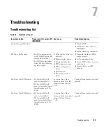

Troubleshooting
86
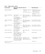
IM status LED amber
1
MAC address missed or
incorrect.
2
I
2
C communication fail.
1
Set MAC address using
llcDebug command if its
incorrect or missed.
2
Ensure there is no HW
damage.
BC status LED blinking
amber
LED will blink on every 1s
interval and
‘LastUpgradeStatus’
property on Bc target will
show CFGERROR.
Different Infrastructure
property between BC and
MC (G5/G5.5).
Ensure both BC and MC have
same Infrastructure property.
IM status LED blinking
amber
LED will blink on every 1s
interval and
‘LastUpgradeStatus’
property on IM target will
show CFGERROR.
Different Infrastructure
property between IM and
MC (G5/G5.5).
Ensure both IM and MC have
same Infrastructure property.
MC Error LED blinking
amber
LED will blink on every 1s
interval and
‘LastUpgradeStatus’
property on Rack target will
show CFGERROR.
Different Infrastructure
property between IM, MC
and BC (G5/G5.5).
Ensure IM, MC and BC have
same Infrastructure property.
MC Error LED amber
MC will dump log in
llcEvent.log file.
Ethernet link to IM is
down.
Ensure LAN connection is fine.
PSU status LED amber
MC will send PSU fault
bitmap to iDRAC through
BC and MC will display
PSU Error status on MC
CLI under PSU target.
PSU fail.
OCP, OVP, OTP.
G5.5 FW update fail
BC/IM will send fail status
to MC and MC will dump
the llcEvents log (BC/IM
will not lit Amber LED).
Any image is wrong
(header/checksum) or
update G5 image on G5.5.
1
Call Dell help. Ask if the FW
is official release.
Some server can not boot
after rack power on
1
Reset server.
Table 42. Troubleshooting list (continued)
Issue description
Trigger event for amber LED
(MC/IM/BC)
Root cause
Troubleshooting step
Содержание DSS 9000
Страница 43: ...Bus bar overview 32 Figure 40 Bus bar bottom P positive red Figure 41 Bus bar bottom N negative black ...
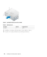
Страница 65: ...Installing and removing system components 54 Figure 64 Removing the fan module ...
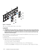
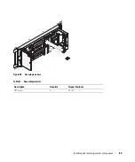
Страница 72: ...61 Installing and removing system components Figure 72 Securing a cable with a cable clip ...
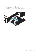
Страница 79: ...Installing and removing system components 68 Figure 80 Installing the BC ...


